
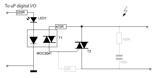
Small Triac Switch
To effectively switch floodlights with an Arduino, a more robust circuit design is essential. The initial approach using the 39MF22, a type of low-power transistor, lacks the capacity to handle the high current typically required by floodlights. A suitable alternative would be to utilize a relay or a solid-state relay (SSR), which can handle higher loads without the risk of overheating or damage.
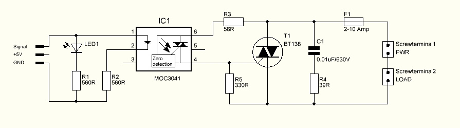
In this revised circuit, the Arduino can control a relay module that is rated for higher current and voltage. The relay module should include an opto-isolator to protect the Arduino from potential voltage spikes. The control side of the relay will connect to a digital output pin on the Arduino, while the load side will connect to the floodlights.
The schematic should include the following components:
1. **Arduino Microcontroller**: This will serve as the control unit, sending signals to the relay module.
2. **Relay Module**: Choose a relay rated for at least 10A at 120V AC (or appropriate for the floodlight specifications). The relay will physically switch the floodlight circuit on and off.
3. **Opto-Isolator**: This component will provide electrical isolation between the Arduino and the high-voltage circuit, enhancing safety.
4. **Diode**: A flyback diode should be placed across the relay coil to prevent voltage spikes when the relay is turned off.
5. **Power Supply**: Ensure that the relay module is powered appropriately, either from the Arduino’s power supply or a separate source, depending on the relay’s voltage rating.
6. **Floodlights**: Connect the floodlights to the relay's normally open (NO) contacts.
The connections should be made as follows: the Arduino pin connects to the input of the opto-isolator, which in turn connects to the relay module. The relay's coil is connected to a power source, and the floodlights are wired to the relay's output terminals. This configuration allows the Arduino to control the floodlights safely and effectively, ensuring reliable operation.
Proper consideration should be given to the layout of the circuit, ensuring that all components are rated for the expected loads and that adequate heat dissipation measures are in place, especially for the relay. This design enhances the functionality and safety of the floodlight control system.In order to switch some floodlights by my Arduino, the small switch circuits I built around a 39mf22 were just not man enough to handle the current ne.. 🔗 External reference
Related Circuits

Operating high-beam headlights while driving on highways can significantly enhance visibility; however, it poses a blinding risk to other drivers. This straightforward circuit can be integrated into the headlight switch to facilitate automatic switching between high and low beam...

The fade circuit controls the lighting switch depicted in Figure 1-12. The figure illustrates the light switch S, H, which is responsible for lighting. Transistors VT1 and VT2, along with RC components, comprise the fade dimming control circuit. Given...
The triac is expected to activate and illuminate the light at nearly 100% brightness; however, it does not turn on at all. If the gate is continuously triggered (i.e., a constant voltage is applied to the gate), the light...
This post presents an interesting topic about switching power supply circuit diagrams for those who wish to learn more. A switching power supply is a type of power supply that uses a switching regulator to convert electrical power efficiently. Unlike...

The image depicts a proximity switch circuit that includes the HMC1001 Hall effect sensor, an operational amplifier (AMP04), and a light-emitting diode (LED). In this configuration, the operational amplifier functions as a comparator. When a magnet with a length...

The current vehicle, a Pajero, has been modified for dual fuel operation, utilizing both petrol and gas. It is essential to operate the vehicle on petrol at regular intervals to prevent clogging of the injectors. This circuit facilitates starting...