
USB Powered Audio Power Amplifier
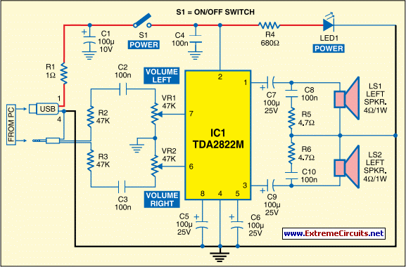
The USB Powered Audio Power Amplifier Circuit is designed to enhance audio output for multimedia speakers connected to personal computers. This circuit operates directly from a USB power source, making it convenient for portable applications and reducing the need for additional power adapters. The core of the amplifier typically utilizes a single-chip audio amplifier IC, which simplifies the design and minimizes component count while ensuring efficiency and performance.
The circuit generally consists of the following key components:
1. **USB Connector**: This component serves as the power input, providing a 5V supply from the USB port of a computer or power bank.
2. **Audio Input**: The circuit accepts audio signals, usually from a 3.5mm jack or a USB audio interface, which is fed into the amplifier IC.
3. **Amplifier IC**: A dedicated audio amplifier chip, such as the PAM8403 or similar, is used to boost the audio signal. These chips are known for their low power consumption and high efficiency, often providing up to 3W output per channel.
4. **Passive Components**: Resistors and capacitors are utilized for biasing, filtering, and coupling the audio signals, ensuring that the output is clean and free from distortion.
5. **Output Stage**: The amplified audio signal is sent to the speakers. Depending on the design, this may include additional components like a low-pass filter to eliminate high-frequency noise and improve sound quality.
6. **Power Management**: Some designs may incorporate a voltage regulator or power management IC to ensure stable operation and protect the amplifier from voltage fluctuations.
The compact nature of this circuit makes it suitable for integration into various multimedia applications, including desktop speakers, portable audio devices, and DIY audio projects. The use of USB power not only simplifies the power supply design but also allows for easy connectivity and portability, making it an attractive solution for enhancing audio performance in a variety of settings.The following circuit shows about USB Powered Audio Power Amplifier Circuit Diagram. Features: multimedia speakers for PCs, has single-chip-based .. 🔗 External reference
Related Circuits
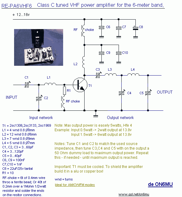
10W HF linear amplifier circuit schematics free electronic circuits diagram wiring design plans schema DIY projects handbook guide tutorial schematic electronic schematic diagram project electronic schematic circuit diagram. The 10W HF linear amplifier circuit is designed to amplify high-frequency signals...

A circuit is needed to drive three or more LEDs at a current of 200-350mA each, with the capability to randomly flash or strobe them at a frequency of 5-20Hz. The input power should be low-voltage DC, with a...
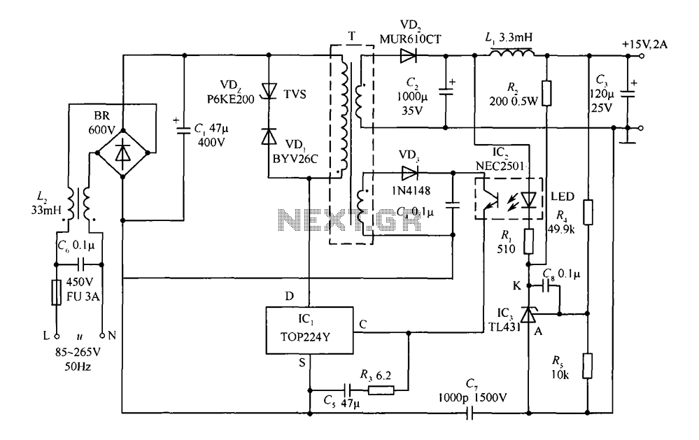
This circuit comprises a 15V TOP224Y, 2A output DC switching power supply. It utilizes three integrated circuits: IC1 is a monolithic regulator (TOP224Y), IC2 is an optocoupler (NEC2501), and IC3 is a precision voltage reference (TL431). The TL431 (IC3)...
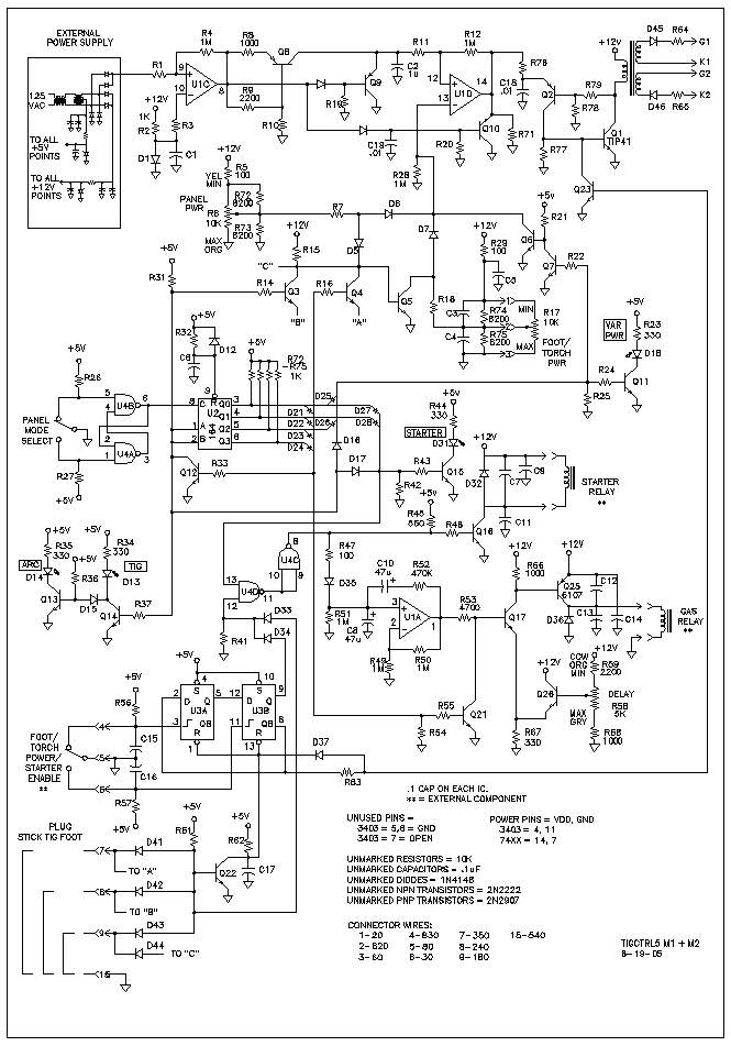
This project began with the exploration of arc starters that could be built at minimal cost using materials typically found in a tinker's workshop. Although it has been an enjoyable endeavor, the extensive collection of items in the basement...
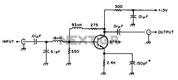
The amplifier delivers a gain of 10 dB across a frequency range of 10-600 MHz and features a 1-to-1 impedance match at 50 ohms. The BFR91 transistor exhibits a noise figure of 1 dB at 500 MHz. The circuit...
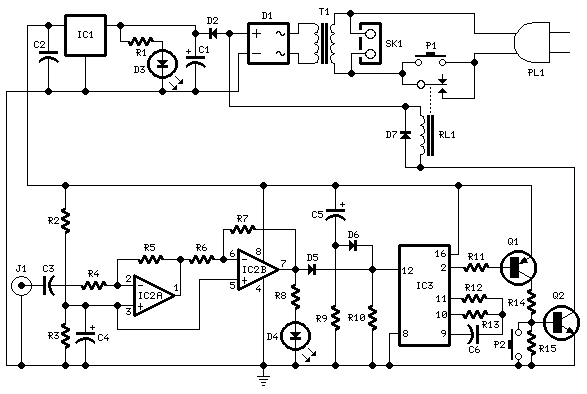
This circuit deactivates an amplifier or other devices when a low-level audio signal at its input is absent for at least 15 minutes. By pressing P1, the device is activated, supplying power to any appliance connected to SK1. The...