
led lighting for 6v vehicles
The proposed circuit design focuses on integrating high-efficiency Lumiled LEDs into the existing motorcycle lighting system, enhancing both performance and reliability. The circuit utilizes a TIP110 transistor configured as a constant current source, ensuring that the LEDs receive a stable current regardless of variations in supply voltage. The inclusion of a heatsink for the TIP110 is crucial to prevent thermal runaway, which can occur due to heat buildup during operation.
The design incorporates a series resistor to manage current flow, with specific values calculated based on the desired current for each light type. The choice of a fixed resistor instead of a variable one is made to maintain reliability over time. The biasing of the TIP110 with a yellow LED ensures consistent performance, while the additional resistors serve to stabilize the flasher unit's operation, ensuring that the lights function correctly during signaling.
The optional capacitor smooths the LED turn-on characteristics, providing a more gradual illumination that mimics incandescent bulbs. This feature addresses potential regulatory concerns regarding the use of LEDs in automotive applications, making the design more compliant with such regulations. Overall, this circuit design represents a significant advancement in motorcycle lighting technology, offering improved efficiency, durability, and safety.This design replaces the incandescent bulbs in the stop, tail and indicator lights of an MZ or other motorcycle with a six-volt electrical system,with high-intensity Lumiled LEDs. This gives the following advantages: A single Lumiled with a power consumption of around 1. 2W gives a light output equivalent to a colour-filtered 21W incandescent bulb. The load on the electrical system is therefore considerably reduced. The power saved may be used to drive a more powerful headlamp bulb. Unlike incandescent bulbs, LEDs do not burn out, and are not affected by vibration. Therefore, they do not need to be replaced. Accordingly, the light units may be permanently sealed and waterproofed with silicone sealant or similar, and connections to the LEDs made by soldered connections rather than contacts. The reliability of the lighting system is therefore much greater than the standard incandescent system.
The colour of the light is determined by the properties of the semiconductor material from which the LEDs are made, and not by filtering with a coloured lens. Therefore, should the lens be damaged or broken in an accident, the lights will continue to show the correct colour.
Unlike an incandescent bulb, an LED requires external circuitry to limit the current taken to a safe value. This is generally done with a simple series resistor. However, this approach is not suitable for a six-volt automotive electrical system. The LED will drop about 3 volts in operation, and the supply voltage may vary from about 5 volts to 7 volts or more depending on the state of charge of the battery and the engine speed.
This would result in a variation of about 2:1 in the voltage across the series resistor, with a consequent 2:1 variation in the brightness of the LED. The current is nominally determined by the value of the emitter resistor of the TIP110. Due to component variations it will be necessary to adjust the value of this resistor to obtain the correct current, which is 320mA for an indicator or stop light and 80mA for the tail light.
Approximately correct currents will be given by using 2. 4 ohms for 320mA, and 10 ohms for 80mA. The actual currents should be measured and the resistor changed in accordance with the result. Use of a variable resistor is NOT recommended, for reasons of reliability. The 2. 4 ohm resistors should be rated at 0. 5W. Note that the absolute maximum permitted current for a Lumiled is 350mA. Heat dissipated in the TIP110 has the unfortunate effect of causing the regulated current to rise. To avoid this the TIP110 should be heatsunk. This is most easily done by building the circuit in a diecast metal box and bolting the TIP110 to the box with suitable insulating washers and thermal transfer grease. The purpose of the yellow LED is to provide the bias voltage for the constant current source. A green LED could be used instead, but a red or blue LED would NOT be suitable. There is no requirement for these bias LEDs to be visible. The two series 47 ohm resistors across the entire circuit are to ensure correct operation of the flasher unit (see later).
A single 100 ohm 0. 5 watt resistor will do just as well. They are not required in the stop or tail lights. The 470uF capacitor is optional and may be left out if desired. Its purpose is to cause the LED to turn on gradually, in a similar manner to an incandescent bulb, and thereby disguise the fact that an LED is fitted. This may be thought desirable in order to avoid possible problems due to incredibly stupid regulations which forbid the use of LEDs for vehicle lights unless incandescent bulbs are also fitted as the primary light source.
(If anyone responsible for such regulations is reading this: GET A CLUE ALREADY. ) I 🔗 External reference
Related Circuits
The heating element is connected in series with two back-to-back 16 amp silicon-controlled rectifiers (SCRs), which are controlled by a small pulse transformer. This pulse transformer features three identical windings; two of these windings provide trigger pulses to the...
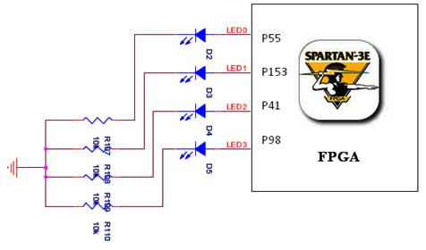
The Spartan-3E board features four LEDs connected to FPGA I/O pins, as detailed in the accompanying table. Each LED's cathode is connected to ground through a 330-ohm resistor. To illuminate a specific LED, the corresponding FPGA control signal must...
This circuit provides a visual 9-second delay using 10 LEDs before closing a 12-volt relay. When the reset switch is closed, the 4017 decade counter resets to the 0 count, illuminating the LED driven from pin 3. The 555...

Designing a controller PCB for a 10x10 white LED matrix clock based on an ATmega328 AVR IC and a Maxim DS3234 SPI RTC. The challenge lies in controlling a custom non-standard 10x10 LED matrix. Initially, a Maxim MAX7219/7221 IC...
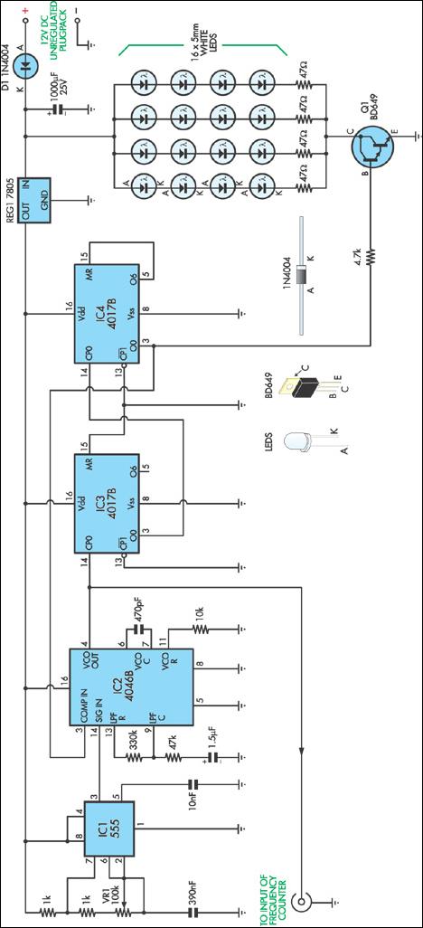
This stroboscope circuit employs 16 high-brightness white LEDs housed in a torch and provides a signal output to a frequency counter for rev counter display. The circuit utilizes IC1, a 555 astable multivibrator, which generates a signal for IC2,...
Catalyst Semiconductor, Inc. (NASDAQ:CATS), a supplier of analog, mixed-signal, and non-volatile memory semiconductors, announced it has received a patent for a unique step-down switching regulator circuit architecture applicable to step-down regulators for driving high brightness LEDs. The patent, titled...