
pcb Driving 10x10 LED matrix with AVR

The project involves creating a printed circuit board (PCB) to control a 10x10 LED matrix clock. The core of the design is based on the ATmega328 microcontroller, which is a popular choice for embedded applications due to its versatility and ease of programming. The Maxim DS3234 is utilized as a real-time clock (RTC), facilitating accurate timekeeping.
To manage the 10x10 LED matrix, which consists of 100 individual white LEDs, a suitable driving mechanism must be implemented. The initial plan to use the MAX7219 or MAX7221 integrated circuits is not feasible, as these components are designed to handle only 8x8 matrices. Therefore, alternative approaches must be considered to effectively control the larger matrix.
One potential solution is charlieplexing, a technique that allows for the control of multiple LEDs using fewer pins by exploiting the tri-state logic of microcontroller I/O pins. This method is particularly advantageous for large matrices but requires careful planning of the circuit layout and programming logic to ensure that the correct LEDs are illuminated without unintended activations.
The ULN2803 darlington transistor array can be employed to handle the higher current requirements of the white LEDs, which necessitate at least 30mA for optimal brightness. The ULN2803 consists of eight darlington pairs, allowing it to control multiple LED rows or columns efficiently. Each output of the ULN2803 can sink significant current, making it suitable for driving the LEDs directly from the microcontroller.
In summary, the design of the controller PCB for the 10x10 LED matrix clock requires a combination of the ATmega328 microcontroller and the DS3234 RTC, along with a charlieplexing scheme and the ULN2803 transistor array to achieve the desired functionality and brightness of the LEDs. Careful consideration of the circuit design, including the arrangement of the LEDs and the programming of the microcontroller, will be essential to ensure reliable operation and performance of the clock display.Designing a controller PCB for a 10x10 white LED matrix clock (inspired by the tutorial here ). It`s based off an ATmega328 AVR IC and Maxim DS3234 SPI RTC. However, I`m stuck: I have no idea how to control my custom non-standard 10x10 LED matrix. Originally I was going to use a Maxim MAX7219/7221 IC, but it can only drive 8x8 LED matrices. Then I was looking at some sort of charlieplexing solution with a ULN2803 darlington transistor array. The bright white LEDs I`m using need at least 30mA of current. 🔗 External reference
Related Circuits
The remote control transmits encoded signals. Each time a key is pressed, the relevant code is transmitted, usually repeating it many times to ensure reception. This encoded signals travels over a radio or infrared-light beam, to eventually get captured...
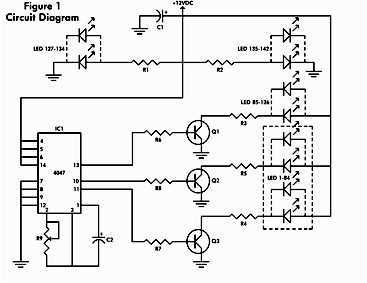
It consists of a 4047 low-power monostable/astable multivibrator, IC1, used in the astable mode to provide the timing pulses to control the flash rate of the LEDs. To accomplish the astable mode, pins 4, 5, 6, and 14 are...
This circuit is a small digital roulette. It is constituted by oscillator IC1, the counter IC2, the transistors Q1-7 that drive the display common cathode DSP1. The supply basically becomes from a battery 9V, but can become also from...
A project called LED Flasher that sequentially flashes LEDs one by one. There is a query regarding the project, and any simple explanation would be greatly appreciated. A reference image or a link can be used for additional context. The...
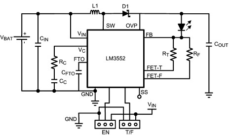
For this LED driver electronic project, a DC power supply circuit is required to provide an output voltage between 2.7V and 5.5V. The supply voltage must be applied between Vin and GND. The T/F jumper connects the T post...
There are many posts on Instructables detailing how to create a flickering LED candle. This version of the project requires several components. The flickering LED candle project aims to simulate the warm glow and flicker of a real candle using...