
Temperature ControlCircuit using Microcontroller and Heater Driver
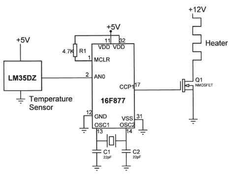
The temperature control circuit utilizes the LM35DZ, a precision analog temperature sensor that outputs a voltage proportional to the temperature in degrees Celsius. This sensor operates within a range of -55°C to +150°C, providing a linear output of 10 mV/°C. The analog signal from the LM35DZ is fed into the PIC16F877 microcontroller, which features an integrated 10-bit A/D converter. The microcontroller processes the analog temperature data, converting it into a digital signal for further manipulation and control logic execution.
The PIC16F877 is programmed to monitor the temperature readings and compare them against predefined thresholds. Based on this comparison, the microcontroller generates control signals to activate or deactivate the heater driver, which in this case is the IRL1004. This MOSFET driver is capable of handling high currents and voltages, making it suitable for controlling heating elements. The IRL1004 operates efficiently due to its low on-resistance, ensuring minimal power loss during operation.
The circuit is designed with appropriate power supply decoupling and filtering to ensure stable operation of the microcontroller and the sensor. Additionally, it includes necessary protection components, such as diodes, to safeguard against voltage spikes that may occur during the switching of the heater. Overall, this temperature control circuit provides a reliable and efficient solution for maintaining desired temperature levels in various applications.The electrical circuit diagram of this temperature control circuit consists 3-pin analog temperature sensor (LM35DZ), a built-in A/D converter microcontroller (PIC16F877), and the heater driver (IRL1004) 🔗 External reference
Related Circuits
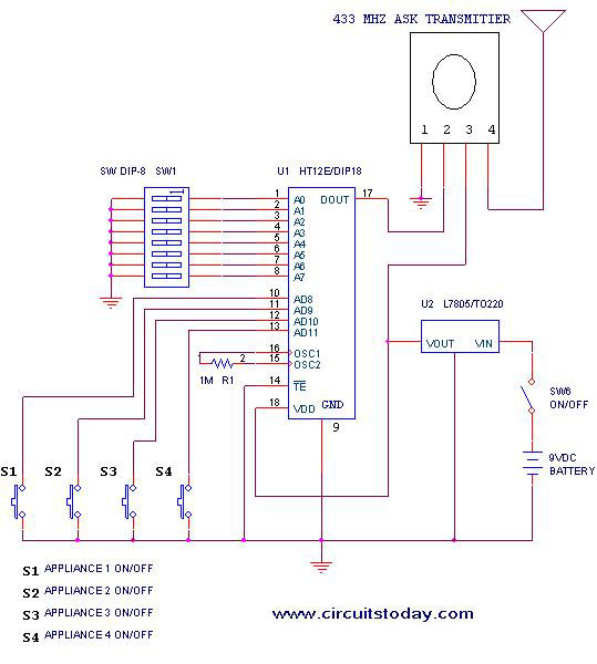
This project outlines a simple remote control system utilizing RF communication without the use of a microcontroller. The remote is designed for various home appliances such as televisions, fans, and lights, providing significant convenience by allowing operation from a...
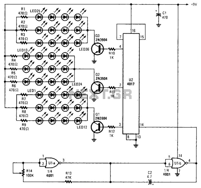
Originally designed as a three-bell animation circuit for Christmas decorations, this circuit can also be utilized for various other applications that require a flashing effect. By reconfiguring U2 (refer to the data manual), it is possible to achieve more...
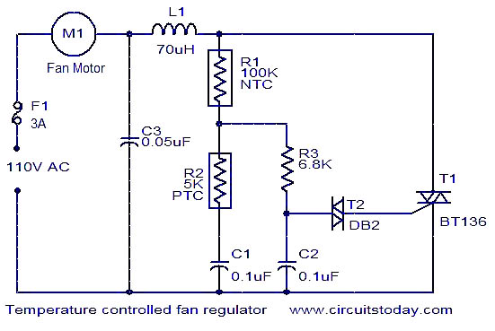
The function is designed to automatically control the speed of a fan based on the temperature. Components include a BT136 Triac, capacitor, resistor, relay, and fan motor. The circuit employs a temperature sensing mechanism to monitor ambient temperature levels. A...

This is a single-zone alarm system equipped with automatic exit, entry, and siren cut-off timers. It can accommodate various types of normally-closed input devices, such as magnetic reed contacts, foil tape, and passive infrared sensors (PIRs). Additionally, it is...

The solar orientation circuit employs a comparator with window control to maintain engine idle as long as the two LDRs (light-dependent resistors) are exposed to equal illumination. In this scenario, half the supply voltage is applied to the non-inverting...

A low-cost, simple radio circuit schematic using an operational amplifier. This radio circuit diagram consists of a sensitive audio amplifier that receives strong signals. The presented radio circuit schematic utilizes an operational amplifier (op-amp) to create a cost-effective and straightforward...
Warning: include(partials/cookie-banner.php): Failed to open stream: Permission denied in /var/www/html/nextgr/view-circuit.php on line 713
Warning: include(): Failed opening 'partials/cookie-banner.php' for inclusion (include_path='.:/usr/share/php') in /var/www/html/nextgr/view-circuit.php on line 713