
up down led sequencer

The design of the LED bar graph circuit can effectively utilize the LM3914 in bar mode, providing a straightforward method for sequentially illuminating the LEDs. The triangular ramp voltage applied to the input of the LM3914 is critical for achieving the desired sequential lighting effect. The ramp voltage should be generated with a stable waveform to ensure consistent timing for each LED. However, the challenges faced with the 555 timer indicate that an alternative waveform generator or a more stable control circuit may be necessary for precise control over the timing and illumination duration of the LEDs.
Transitioning to a digital approach with the CD40194 shift register offers a robust solution that can simplify the control of the LEDs. Each LED can be driven by the outputs of the shift register, which can be easily expanded by cascading multiple CD40194s if more than four LEDs are required. The clock pulses can be generated using a simple oscillator circuit, which can be designed to provide the necessary frequency for illuminating the LEDs at the desired speed.
The control logic for the shift register can be implemented using a flip-flop that toggles its state based on a counter, determining whether to shift the output to the right or left. This allows for a seamless transition from lighting the LEDs to extinguishing them, creating an appealing visual effect. Care should be taken to ensure that the control signals are debounced to prevent erratic behavior during operation.
In summary, this circuit design combines both analog and digital techniques to create a visually engaging LED bar graph display. The choice between using the LM3914 or the CD40194 shift register will depend on the specific requirements for timing, control, and complexity, but both methods offer viable paths to achieve the desired sequential lighting effect.I have a 10 light LED bargraph, I want to make the LED`s light one after the other until all the LED`s are lit, and then have the circuit cycle back down until all the LED`s are off again. A simpler (analog) way is a LM3914 - Dot/Bar Display Driver operating in the bar mode. If you put a triangular ramp voltage at the input, the LEDs will light up in sequence, and then go out in sequence. I`ll have to order some cd4011`s tomorrow. I only have a few cd4013`s in my parts bin. I`ll look at the data sheets and see if I can improvise. Thanks for the schematic Collin55. I built a circuit using a LM3914. The only problem I ran into was using a 555 as a triangle wave generator. The top and bottom LED`s would stay lit for a disproportionate time, and it was hard to adjust the span and time constant. If I turned one pot it would affect the range on the other. That`s why I tried building the circuit using the 4017. I wanted to make something that would use a pulse instead of depending on a changing voltage. I was hoping to make the flow seem more constant. I`ll also look into the function generator chips Crutschow, might be a good alternative to a 555, especially since I`m trying to run it at a very low frequency.
Boncuk, 5 LED`s would be fine. I`ve been searching high and low for a circuit I could use to do this, but all I could find was a Knight Rider circuit. Do you have a schematic One digital approach would be to use a bidirectional shift register such as the 4-bit CD40194.
You can connect as many in series as you need. You would connect the LEDs to the shift-register parallel outputs (through drivers). Then you connect the "shift right" direction to logic high ("1"). This will sequentially illuminate each LED on each clock pulse. When you get to the last LED you reverse the shift direction, with the "shift left" connected to "0". This will sequentially turn off each LED. You will need some logic to generate the up/down control signal for the shift-register. The could consist of a flip-flop that controls the direction with its state changing at the beginning count and the end count.
acquiring knowledge is like doing a jig saw puzzle, many of the bits on their own dont make sense, but they are all needed to give a complete picture. "Eric Gibbs" I don`t see a big difference between using a pull down resistor and omitting it. At VDD=12V and a pull down resistor of 10K © the base voltage is 3. 97274e-08 with a low counter output. Without pull down resistor it is 5. 20027e-06 which are both far below any voltage to allow collector current flow. LEDs 1 and 5 which are switched without diodes have a low level base voltage of 2. 7623e-08. 🔗 External reference
Related Circuits

The schematic for this project is visually acceptable, although it is not the most refined layout for a schematic. The basic flow progresses from left to right, starting with the state machine, followed by the 555 timers, then the...
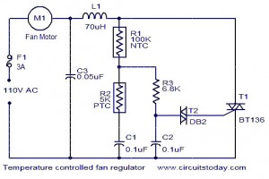
The function for automatically controlling the speed of a fan according to the temperature. Components: BT136 Triac, Capacitor, Resistor, Relay, Fan Motor. This circuit is designed to automatically adjust the speed of a fan based on the ambient temperature. It...

A mobile-controlled robot is a mobile device that offers extensive wireless control capabilities to the robot, as long as the cell phone remains within signal range. The mobile-controlled robot operates through a wireless communication interface, typically utilizing Bluetooth or Wi-Fi...
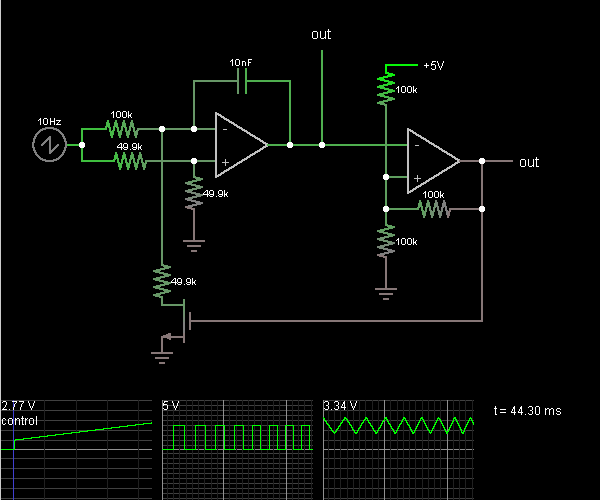
This circuit is a voltage-controlled oscillator, which is an oscillator whose frequency is determined by a control voltage. A 10 Hz sawtooth oscillator provides the control voltage in this case; this causes the frequency to rise slowly until it...
This indicator can be used, or see if your speakers can be damaged by the noise power. With P1 you can set the limit to which D1 LED lights. The pot is 100k here, you can even experiment with...
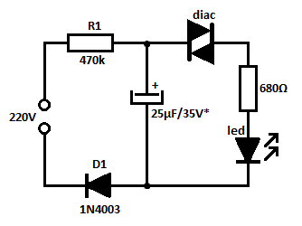
This is likely the simplest concept for generating a flashing light from an LED using alternating current (AC). The circuit provides a straightforward method for flashing one or more LEDs using high-voltage direct current (DC) sourced from mains electricity....