
LED monitor for 12V Battery
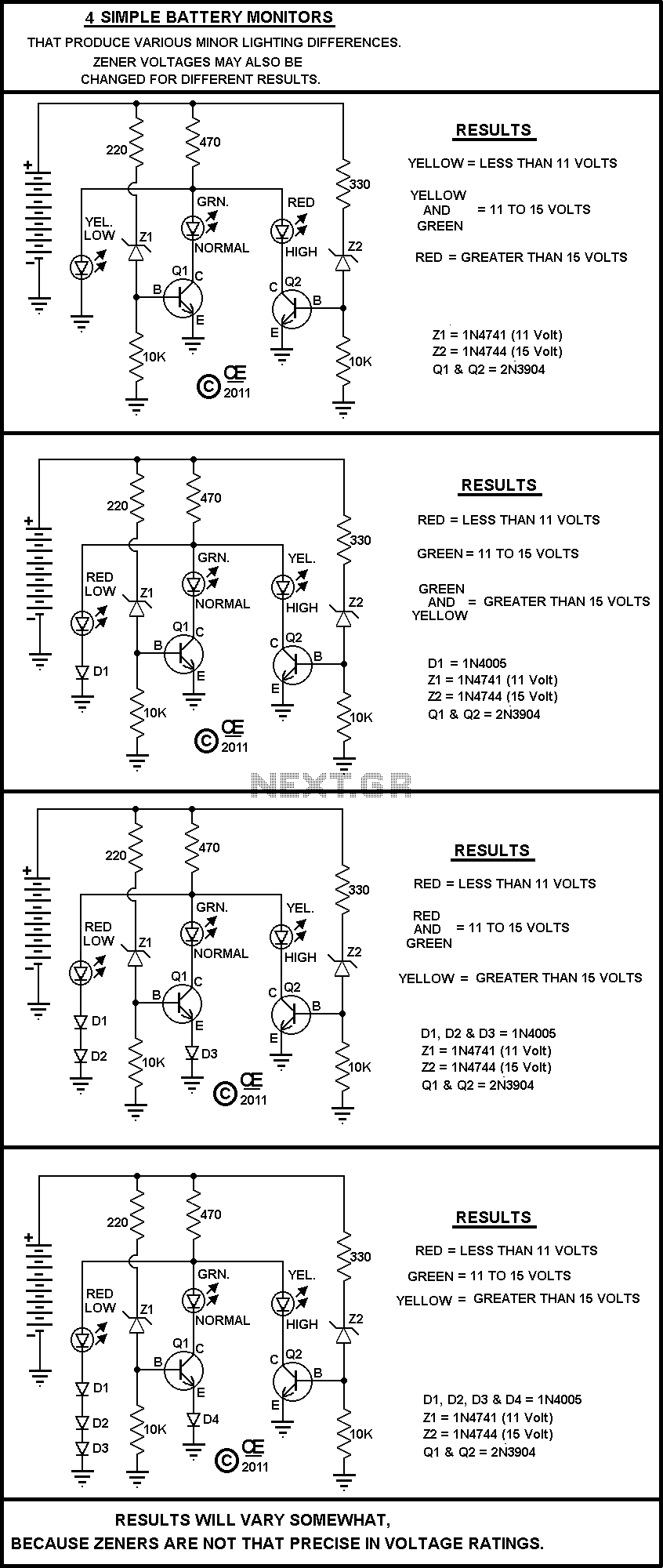
All parts are cheap and should be easily obtained. None are very critical.
The circuit in question is a basic electronic assembly designed for educational purposes and experimentation. It typically consists of fundamental components such as resistors, capacitors, diodes, and possibly a simple microcontroller or an operational amplifier, depending on the intended variations. The simplicity of the design allows for modifications and enhancements, making it an excellent platform for learning and prototyping.
The schematic may feature a power supply, which could be a battery or a DC power adapter, providing the necessary voltage and current for the circuit operation. The use of low-cost components ensures accessibility for hobbyists and students. For instance, a resistor can be used to limit current, a capacitor for filtering or timing applications, and a diode for rectification or protection against reverse polarity.
Variations of the circuit could include different configurations, such as changing resistor values to modify current flow or altering capacitor values to change timing characteristics in an RC circuit. Additional features could be incorporated, such as LED indicators for visual feedback or switches for user interaction.
This circuit serves as a foundation for various applications, including simple light control, audio signal processing, or basic sensor interfacing. The versatility of the components allows for numerous configurations, promoting creativity and practical understanding of basic electronic principles. Overall, this simple circuit exemplifies the core concepts of electronics and encourages experimentation with minimal investment.A Very Simple circuit and some Variations. Play with it. All parts are cheap and should be easily obtained. None are very critical. 🔗 External reference
Related Circuits

This circuit is designed for general-purpose use with a large LED display utilizing SPI serial interfacing. It employs a serial-in-parallel-out shift register, specifically the 74HC595, to receive serial data from a microcontroller board. The schematic wiring indicates that SER...
The following circuit illustrates an Emergency Light with a Battery Charger Circuit Diagram. Features include automatic activation of the light when mains power is available. The Emergency Light with Battery Charger Circuit is designed to provide illumination during power outages...
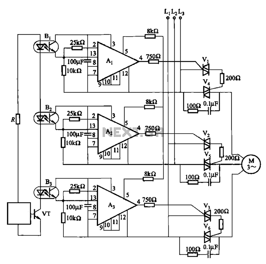
The 331 circuit depicted in the figure utilizes a two-way thyristor for controlling the start and stop functions of a motor. It operates without mechanical contacts, generating no noise or sparks, making it suitable for applications that require frequent...
This circuit allows a 12v relay to operate on a 6v or 9v supply. Most 12v relays need about 12v to "pull-in" but will "hold" on about 6v. The 220u charges via the 2k2 and bottom diode. When an...
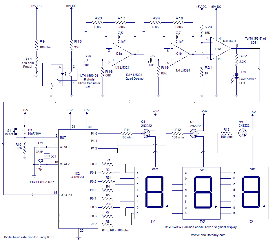
Heart rate monitor using an 8051 microcontroller. It measures the heart rate from the fingertip using an IR diode and phototransistor pair (Photoplethysmography). The AT89S51 microcontroller is utilized in this application. The heart rate monitor circuit operates based on the...
Its based on inductive pickup and very easy to install. Have a look at the pic. (remove LED and connect transistor collector to pin4). I hope it will exactly suits to your tachometer. More: I found your PIC project...