
Emergency Light With Battery Charger
The Emergency Light with Battery Charger Circuit is designed to provide illumination during power outages while simultaneously ensuring that the battery remains charged when mains power is available. The circuit typically consists of a light-emitting diode (LED) or a compact fluorescent lamp (CFL) as the light source, a rechargeable battery, a charging circuit, and a control mechanism that automatically switches the light on when the mains power fails.
The primary components of the circuit include:
1. **Light Source**: An LED or CFL is utilized for its energy efficiency and long lifespan. The choice of light source will depend on the intended brightness and power consumption.
2. **Rechargeable Battery**: A sealed lead-acid (SLA) battery or lithium-ion battery is commonly used to store energy. The battery capacity should be selected based on the desired backup time and the power rating of the light source.
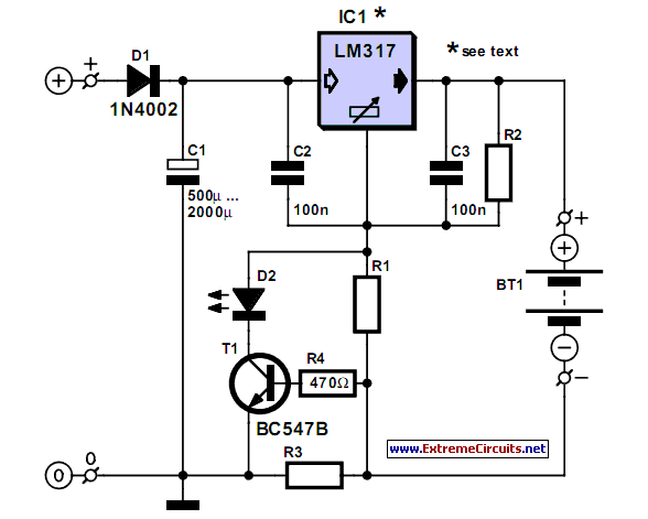
3. **Charging Circuit**: This circuit is responsible for charging the battery when mains power is available. It typically includes a transformer to step down the voltage, a rectifier to convert AC to DC, and a voltage regulator to ensure the battery is charged at the appropriate voltage level.
4. **Control Mechanism**: A relay or a transistor can be employed to switch the light on automatically when the mains power is lost. This mechanism detects the absence of mains voltage and activates the light source using the stored energy from the battery.
5. **Indicator LED**: An additional LED may be included to indicate the status of the circuit, such as whether the battery is charging or if the system is in emergency mode.
The circuit is designed to be compact and efficient, ensuring that the emergency light operates seamlessly during power interruptions, providing essential lighting for safety and convenience. Proper thermal management and component ratings are crucial to ensure reliability and longevity of the circuit during operation.The following circuit shows about Emergency Light With Battery Charger Circuit Diagram. Features:automatic switching-on of the light on mains .. 🔗 External reference
Related Circuits
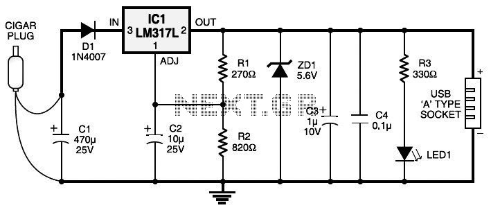
Currently, nearly all computer systems include logic blocks designed for interfacing with a USB port. In practical terms, a USB port can provide more than 100 mA of continuous electric current at 5V to the peripherals connected to the...
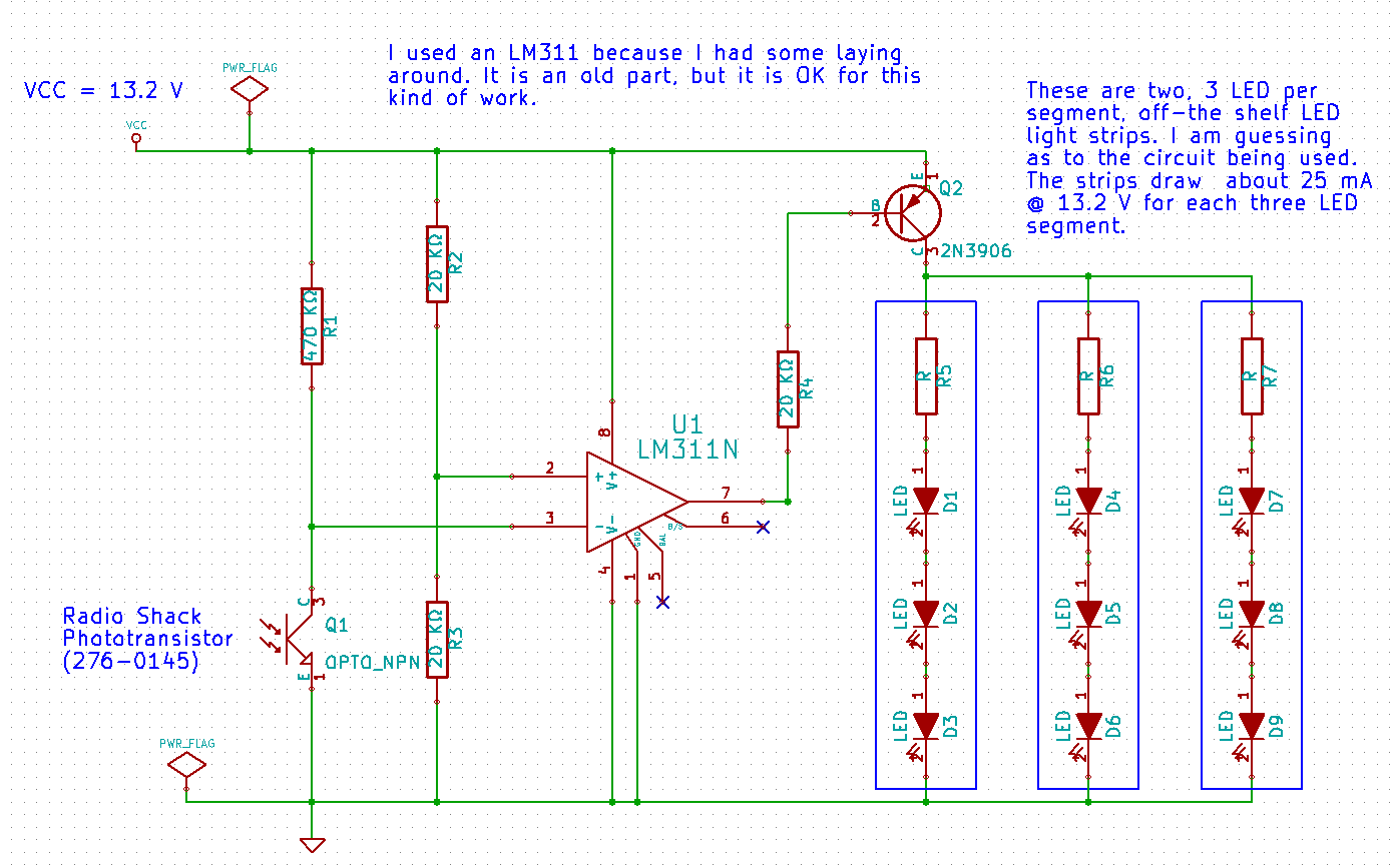
Several individuals have mentioned that the house number is difficult to read at night. The number comprises four digits mounted on a structural column that supports a section of the roof. In response to these concerns, a request has...
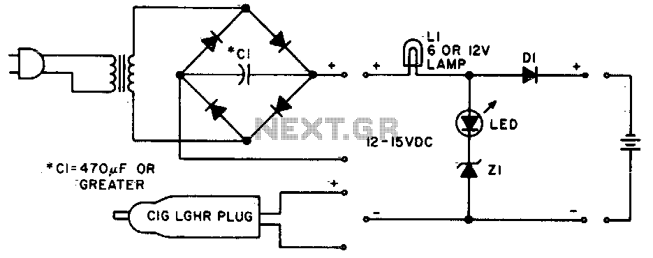
Lamp LI will glow brightly while the LED remains off when the battery is low and charging. Conversely, the LED will illuminate brightly, and the light bulb will be dim when the battery is nearly charged. Lamp LI should...
A simple NiCd charger can be constructed using readily available components and an economical LM317 or 78xx voltage regulator. The design incorporates a current limiter made up of resistor R3. The proposed NiCd charger circuit utilizes an LM317 or a...
A complete guide to addressing challenging electrical system tests in modern vehicles. This resource serves as a comprehensive tool for resolving issues related to the check engine light. Obtain information from a professional technician today. The electrical system in contemporary vehicles...
This circuit performs a rapid battery test without requiring a power supply or costly moving-coil voltmeters. It offers two testing ranges: when switch SW1 is positioned as indicated in the circuit diagram, the device can test batteries ranging from...