
Switch off delay circuit by 2N4871
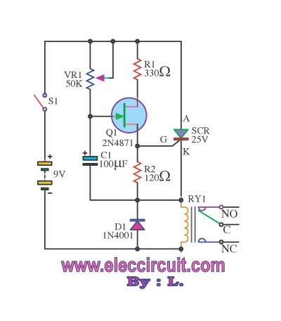
The surge protection circuit is designed to safeguard sensitive electronic devices from voltage spikes that can occur during power outages or fluctuations. The core functionality of this circuit involves a surge protector that detects abnormal voltage levels and responds by disconnecting the load from the power source.
Key components of the circuit typically include a voltage sensor, a relay or a transistor switch, and a fuse. The voltage sensor continuously monitors the incoming voltage level. When the voltage exceeds a predetermined threshold, indicating a surge, the sensor triggers the relay or transistor to open the circuit, effectively disconnecting the load.
In addition, the circuit may incorporate a capacitor and a resistor to smooth out any transient voltage spikes. A fuse is also included to provide an additional layer of protection, blowing in the event of a sustained overcurrent condition, thus preventing damage to the circuit components and connected devices.
The design may also feature an indicator LED that illuminates to signal when the circuit is in surge protection mode, providing a visual cue to the user. For enhanced reliability, the circuit can be housed in a durable enclosure that protects it from environmental factors such as dust and moisture.
Overall, this surge protection circuit plays a critical role in maintaining the integrity and longevity of electrical appliances by ensuring they are shielded from harmful voltage fluctuations.This circuit prevents surges. From the opening is switched off or power failure. The damage to electrical appliances. The circuit will switch to use a short.. 🔗 External reference
Related Circuits
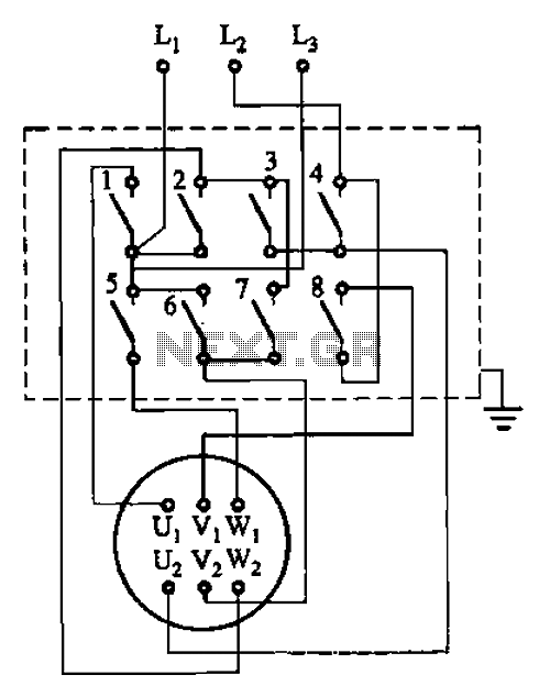
The circuit illustrated in Figure 3-36 includes the starter contact closure detailed in Table 3-1. In the figure, U1, V1, W1, and U2, V2, W2 represent the first three-phase stator windings of the motor terminals. The circuit depicted in Figure...
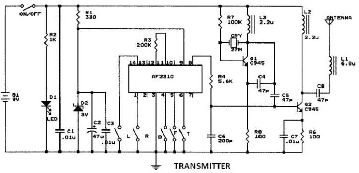
This circuit resembles that of a car radio-controlled toy with seven control functions: forward, forward-left, forward-right, backward, backward-left, backward-right, and stop. Additionally, this radio frequency circuit can be utilized for other electronic circuits that require a simple wireless motor...

This display driver circuit illustrates how a Seven Segment Display is driven using the 5-stage Johnson decade counter IC CD4033. The integrated circuit functions as a counter. The CD4033 is a versatile decade counter that can be utilized to drive...
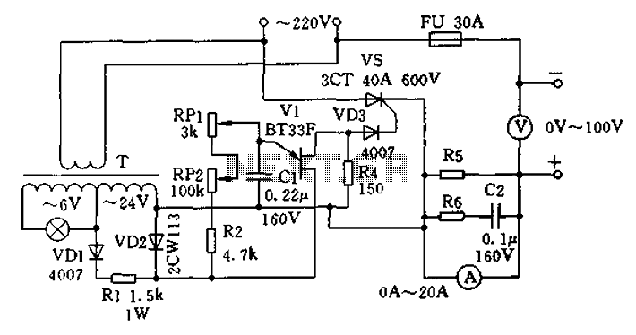
The charging apparatus depicted in the schematic circuit has a maximum output current of 20A and a maximum charging voltage of 80V. It can be adjusted starting from 0V, making it suitable for charging various types of batteries. The...
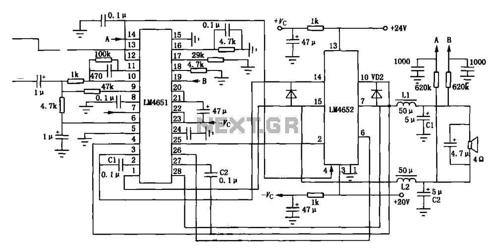
Figure (a) illustrates a 170W output amplifier circuit designed for a 4-ohm load. The LM4651 is a class D amplifier presented in a 28-pin DIP package, with its internal equivalent circuit depicted in Figure (c). The 170W output amplifier circuit...
A video switcher circuit is required to display multiple sources on a single monitor. The circuit schematic below features the MAX454, which serves as the core component of this video switcher. The MAX454 is a video multiplexer-amplifier manufactured by...