
Time to start reversing relay control circuit
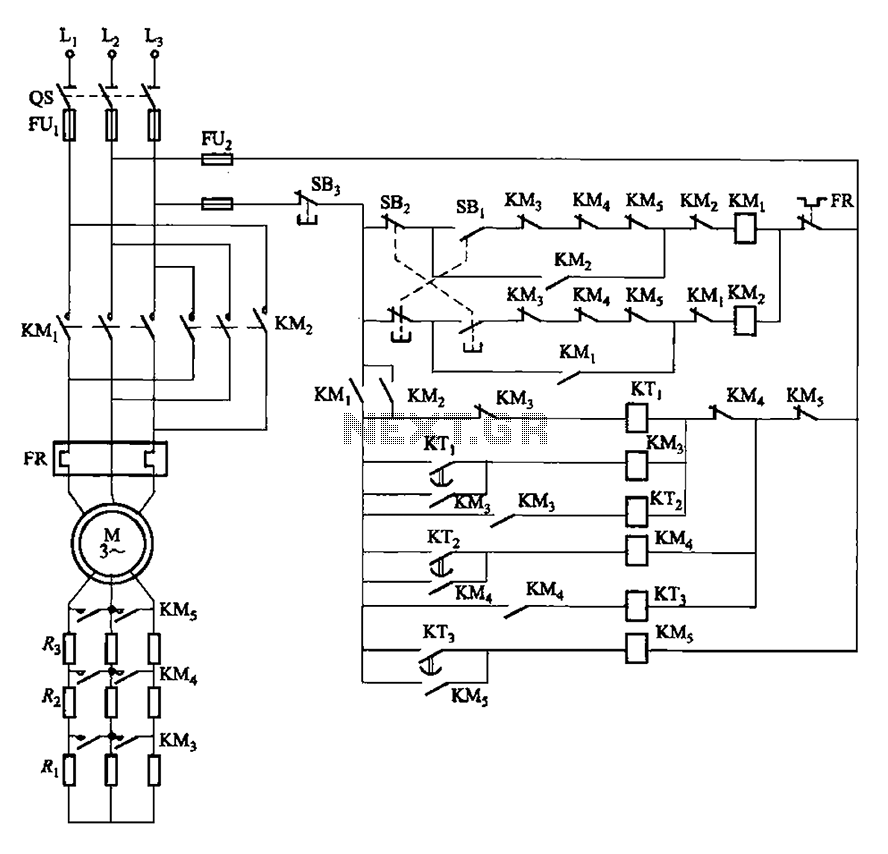
The circuit design incorporates three primary push-button switches: SBi, SBz, and SB3, each serving distinct functions in the operation of the system. SBi, the forward start button, initiates the forward motion of the connected load, while SBz, the reverse start button, allows for reverse operation. SB3, the stop button, halts all operations when pressed.
The time relay units, KTi and KTa, play a critical role in controlling the resistance levels associated with the start buttons. These relays are responsible for timing operations, ensuring that the resistance values are adjusted based on the required operational time intervals. This feature allows for precise control over the speed and direction of the system, enhancing performance and safety.
The configuration of the circuit ensures that pressing the start buttons activates the corresponding relay, which then modifies the resistance in the circuit. This modification influences the current flow to the motor or load, dictating its operational behavior. The design may also incorporate additional safety features, such as interlocks or emergency stop mechanisms, to prevent accidental activation or ensure safe operation during maintenance.
Overall, the circuit is designed for efficient control of a motorized system, allowing for both forward and reverse motion with the ability to stop on demand. The integration of time relays adds a layer of complexity that enhances functionality and adaptability in various applications. Circuit shown in Figure 3-162. in graph. SBi is forward the start button, SBz to reverse the start button, SB3 for the stop button. Start switching resistance levels are contro lled by time relay KTi ~ KTa.
Related Circuits
Circuit diagram for a mini emergency lamp. This mini emergency lamp activates during power failures to provide cool white light in the room. It utilizes a 1-watt white LED to deliver adequate illumination. The circuit for the mini emergency lamp...
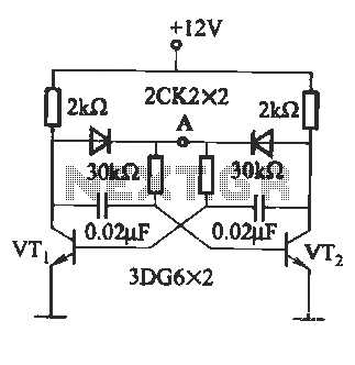
The circuit illustrated in Figure (A) consists of resistors R1 and R2 with values ranging from 15 to 18 kΩ, and capacitors C1 and C2 with capacitance values between 0.01 µF and 10 µF. Figure (B) depicts the oscillation...
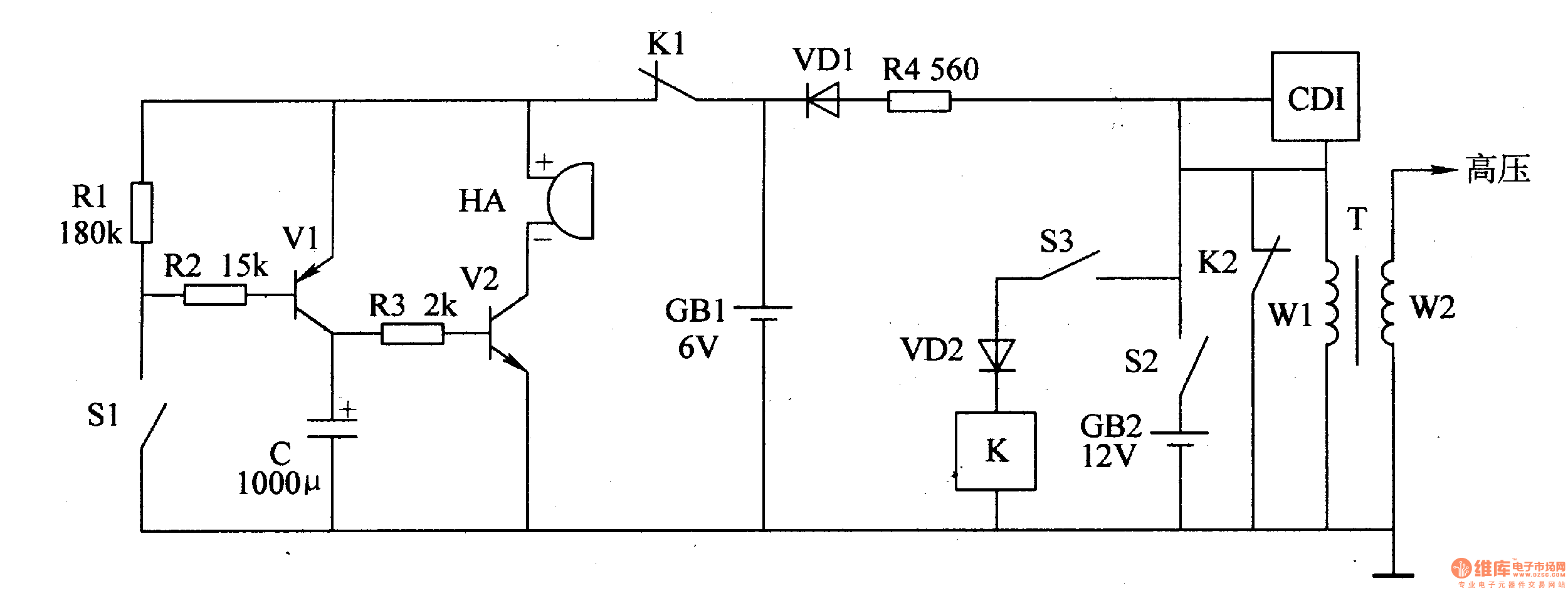
The motorcycle anti-theft alarm circuit consists of a detection alarm circuit, a charging circuit, and an anti-theft control circuit, as illustrated in figure 7-94. The detection alarm circuit includes a mercury switch (S1), resistors (R1-R3), a capacitor (C), transistors...
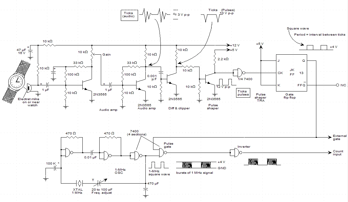
A schematic for a watch timer was found in a hobby electronics book. The circuit adapts a frequency counter to measure intervals. Watch ticks are clipped, shaped, and formed into a square wave. This square wave is utilized to...
Introduction The MIC2290 is an internally compensated standard step-up switching regulator that features an integrated power switch and Schottky diode. The inclusion of these components makes the MIC2290 an optimal solution for 48V Avalanche Photo Diode (APD) applications. In...

This lie detector circuit provides two readings: one for difficult questions and another for the subject's general emotional state. Two flexible, uninsulated wires wrapped around the fingers or wrist can serve as electrodes. Each change in resistance, and consequently...
Warning: include(partials/cookie-banner.php): Failed to open stream: Permission denied in /var/www/html/nextgr/view-circuit.php on line 713
Warning: include(): Failed opening 'partials/cookie-banner.php' for inclusion (include_path='.:/usr/share/php') in /var/www/html/nextgr/view-circuit.php on line 713