
led protection
Figure 1 illustrates a circuit modification of the typical LM317-based current source, incorporating R2 and R3, while maintaining the same operational principles. Typically, the adjust terminal connects directly to the load side of the resistor, ensuring that the circuit functions effectively within the specified parameters. Proper selection of resistor values and attention to thermal management is essential for the reliability and performance of the LED in various applications.All optical transmitters will contain circuitry to limit the current to a value that will be safe enough to protect the LED during short-term accidents. Red, Red-Orange, and Amber Luxeon I LEDs have a much lower peak current rating - about 550 mA. At this lower current, R1 would need to be above 2. 5 ohms and R2/R3 would be adjusted accordingly. If a precise value of R1 (around 2. 2 ohms) can be selected, R2 and R3 can be eliminated and the "adjust" terminal can be connected directly to the "load" side of R1. This lower current/voltage also means that the total drop of this circuit will be in the 3. 5-4 volt range at the limiting current. Philips is apparently phasing out the Luxeon I, III, and V lines in favor of the lower-power Luxeon Rebel devices.
Since I have not used those other devices, the techniques described here may not directly apply unless the maximum current is appropriately adjusted. For the time being, however, the Luxeon III devices are still available from various sources. The Luxeon Rebel devices have a peak current of 700 milliamps, so a 1. 8 ohm resistor in place of R1 (with R2 omitted and the "ADJ" terminal connected to the "load" side of R1) would be appropriate.
With "ultra high-power" LEDs - that is, those with maximum peak currents in the 10`s of amps - the following methods may not directly apply as the LM317 and similar 3-terminal regulators simply can`t handle the current! In those cases, current-limited supplies, a slightly more elaborate overcurrent protection circuit and plain, ordinary care and common sense are your best defenses against accidentally "killing" an LED!
The simplest current limiter is a series resistor. While simple, it`s somewhat costly in terms of power dissipation and its effectiveness (both in preventing damage and in allowing normal operation) is somewhat dictated by the available supply voltage: Too high a value and the LED cannot be driven to full current. Too low a value and the LED is not adequately protected. If the supply voltage is lower or higher than expected, the effects are similar. A solution to this problem is the use of a common 3-terminal voltage regulator, the LM317. This device is commonly used to regulate voltages, using a simple resistive divider to set the output voltage, but it can also be used as a fairly precise current source.
Even though the "official" rating of the LM317 in the "K" (metal TO-3) or "T" (TO-220 "tabbed) packages is 1. 5 amps, it is perfectly capable of operating at somewhat higher currents than this. One of the features of the the LM317 is its built-in current limiting and a quick peek at the data sheet will reveal that its internal ("room-temperature") current limit is typically 2.
2 amps - but it could be anywhere from 1. 5 to 3. 5 amps. In testing dozen or so devices from different manufacturers made over the past two decades or so I observed that they typically exhibited an absolute current limit in the 2. 25-2. 75 amp area and none limited at less than 2 amps when the device was at room temperature. It is important to note that this "maximum current limit" is only valid when the device is at room temperature.
As the device warms up the "thermal protection" begins to take effect, reducing the maximum available current with increasing temperature. I also observed that at "touchable" temperatures (e. g. temperatures at which one could touch the device for 5 seconds or so before deciding that it was too hot) that the reduction in the maximum current was minimal: It wasn`t until the device got well above about 150 degrees F (about 65 C) that it really started to limit its current.
Figure 1 shows such a circuit. This is a modification of the typical LM317-based current source in that R2 and R3 have been added, but its operation is the same: Normally, the adjust terminal is connected directly to the " 🔗 External reference
Related Circuits
This LED flasher circuit is similar to the previous transistor-based LED flasher but utilizes a 555 integrated circuit as the primary component. The schematic diagram illustrates an LED flasher circuit that produces alternating LED flashing, with distinct flashing periods...
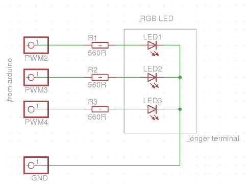
This evening, after returning home from a paragliding appointment, there was a realization that the RGB LED driver code written the previous day needed improvement. The code was refined and annotated extensively for educational purposes. Although the current skill...
A voltage supply ranging from 6 V to 15 V is required when using a single LED per module. An increase in the number of LEDs necessitates a corresponding increase in the voltage supply, with additional LEDs connected in...
This flip-flop circuit is a free-running astable multivibrator, with the bases and collectors of both emitter-biased transistors directly coupled to each other. The switching action is facilitated by a capacitor in each emitter circuit. This configuration produces triangular waves...
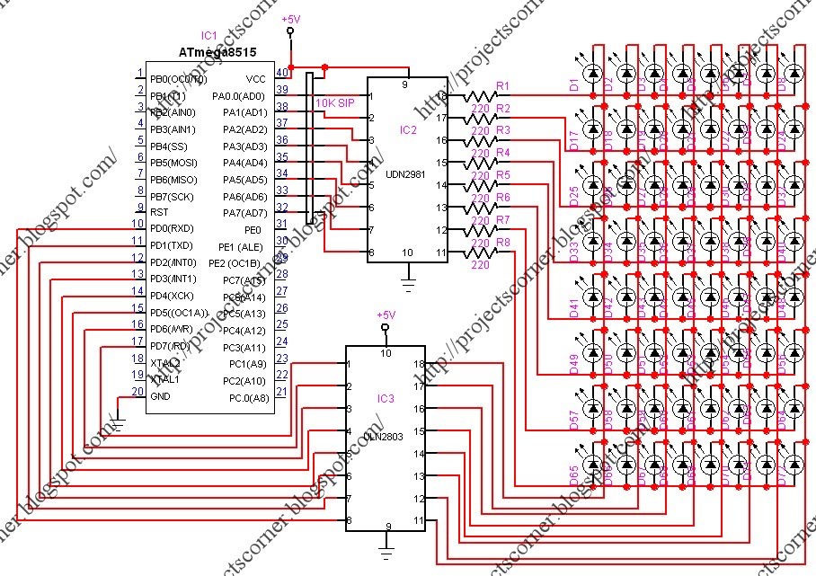
This project involves a scrolling LED display composed of 64 LEDs arranged in a matrix configuration. The anodes of the LEDs are driven by a driver IC, UDN2981, while the cathodes are controlled using the ULN2803. An Atmega8515 microcontroller...
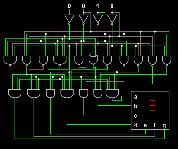
It is possible to implement a circuit using both P-MOS and N-MOS transistors, referred to as CMOS technology. In this context, a three-terminal NAND gate can be constructed. This gate is classified as a universal gate, widely utilized in...