
LED Flasher Using 555 IC

The LED flasher circuit utilizing the 555 timer operates in astable mode, generating a square wave output that alternates between the two LEDs. The 555 timer's output frequency is determined by the resistances R1 and R2, in conjunction with a timing capacitor, typically denoted as C1. The frequency of the flashing can be calculated using the formula:
\[ f = \frac{1.44}{(R1 + 2R2) \cdot C1} \]
In this configuration, R1 and R2 dictate the duty cycle of the output signal, where a higher R2 value results in a longer ON time for LED 1, while the combination of R1 and R2 influences the ON time for LED 2. The use of a variable resistor in place of R1 allows for dynamic adjustments to the flashing rate, making the circuit versatile for various applications.
When only LED 1 is utilized, the removal of LED 2 and R4 not only simplifies the circuit but also enhances the efficiency, as the power drawn from the supply is reduced. By selecting a significantly lower value for R2 compared to R1, the circuit can achieve a rapid ON/OFF switching effect, which is perceived as a strobe light. This strobe effect is often desired in visual signaling applications, where rapid flashes can attract attention or convey information effectively.
In practice, careful selection of the timing capacitor C1 and the resistors R1 and R2 will allow for fine-tuning of the flashing characteristics, enabling the designer to achieve specific visual effects or to match the requirements of particular applications. The 555 timer's reliability and ease of use make this LED flasher circuit an excellent choice for hobbyists and professionals alike, offering a straightforward yet effective solution for LED signaling.This LED flasher give similar circuit with the previous transistor LED flasher, but this circuit use a 555 integrated circuit chip as the active component. Here is the schematic diagram of the LED flasher circuit: This circuit gives alternating LED flashing, but with different flashing period between LED 1 and LED 2.
The ON period of the LED 1 is proportional to the R2 value, and the ON period of the LED 2 is proportional to R1 R2 value. If you use a 1M variable resitor in series with a 22k resitor to replace R1, then you get a variable period flasher. The power consumption will be much lower if you use only LED 1 (remove the LED 2 and R4), and choose R2 value to be much lower than R1.
This would give you a strobe effect since the ON period will be much shorter than the OFF period. 🔗 External reference
Related Circuits
This circuit is a conventional Pierce type oscillator that utilizes a JFET. It employs fundamental mode crystals and demonstrates decent performance and reliability. The Pierce oscillator is a popular configuration for generating stable oscillations, particularly in applications requiring a stable...
A 6-watt audio amplifier circuit utilizing the TDA2613 is presented here. The TDA2613 is an integrated Hi-Fi audio amplifier IC produced by Philips Semiconductors. The IC is designed for high-quality audio amplification. The circuit features the TDA2613 IC, which is...

This reference design converts 90V AC to 135V AC input and drives seven or eight series-connected LEDs with an average current ranging from 300 to 600 mA. The LM3445 operates at a nominal switching frequency of 225 kHz. This...
This circuit uses a germanium diode (marked Ge) as a temperature sensor. I used an OA90 diode but others should do. The 'ring' of Tr1 and Tr2 bias each other. Tr1's collector current is stabilized by the 5v6 zener,...
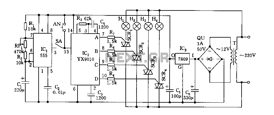
Fantasy lights offer wonderful changes suitable for storage, dance halls, or family holiday decorations. The control circuit is depicted here, which includes a multivibrator control circuit, a thyristor trigger circuit, and a step-down power supply circuit. The AC step-down...
The bi-directional sequencer employs a 4-bit binary up/down counter (CD4516) along with two "1 of 8 line decoders" (74HC138 or 74HCT138) to create the well-known "Night Rider" display. A Schmitt Trigger oscillator generates the clock signal for the counter,...