
LED sequencer
The model 4017 is a versatile CMOS decade counter that operates based on the clock pulses applied to its clock input (pin #14). It features ten output pins (Q0 to Q9), where only one output is high at any given time, creating a unique one-of-ten output pattern. Each pulse at the clock input advances the count, activating the next output in sequence.
The integration of a 555 timer configured in astable mode allows for continuous cycling through the outputs, creating a visual effect with LEDs connected to each output pin. The frequency of the 555 timer can be adjusted by varying the resistor and capacitor values, which in turn influences the rate at which the LEDs flash.
In addition to its primary counting function, the 4017 can be utilized as a frequency divider. This is achieved by connecting the reset pin (pin #15) to one of the output pins, effectively truncating the counting sequence. The output frequency can be calculated based on the clock frequency provided by the 555 timer, allowing for practical applications in various electronic projects.
The reset functionality is crucial for controlling the counting behavior of the 4017. When the reset pin is held high, all outputs reset to low, and the counting sequence halts. The clock enable (pin #1) serves to pause the counting process when set high, providing additional control over the operation of the counter.
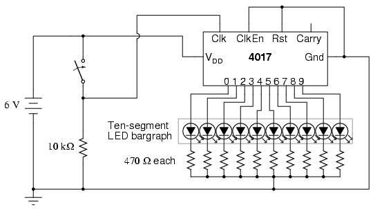
Overall, the 4017 integrated circuit exemplifies a straightforward yet effective solution for creating sequential light displays and frequency division applications, making it a valuable component in electronic design and experimentation.The model 4017 integrated circuit is a CMOS counter with ten output terminals. One of these ten terminals will be in a "high" state at any given time, with all others being "low, " giving a "one-of-ten" output sequence. If low-to-high voltage pulses are applied to the "clock" (Clk) terminal of the 4017, it will increment its count, forcing the next
output into a "high" state. With a 555 timer connected as an astable multivibrator (oscillator) of low frequency, the 4017 will cycle through its ten-count sequence, lighting up each LED, one at a time, and "recycling" back to the first LED. The result is a visually pleasing sequence of flashing lights. Feel free to experiment with resistor and capacitor values on the 555 timer to create different flash rates.
Try disconnecting the jumper wire leading from the 4017`s "Clock" terminal (pin #14) to the 555`s "Output" terminal (pin #3) where it connects to the 555 timer chip, and hold its end in your hand. If there is sufficient 60 Hz power-line "noise" around you, the 4017 will detect it as a fast clock signal, causing the LEDs to blink very rapidly.
Two terminals on the 4017 chip, "Reset" and "Clock Enable, " are maintained in a "low" state by means of a connection to the negative side of the battery (ground). This is necessary if the chip is to count freely. If the "Reset" terminal is made "high, " the 4017`s output will be reset back to 0 (pin #3 "high, " all other output pins "low").
If the "Clock Enable" is made "high, " the chip will stop responding to the clock signal and pause in its counting sequence. If the 4017`s "Reset" terminal is connected to one of its ten output terminals, its counting sequence will be cut short, or truncated.
You may experiment with this by disconnecting the "Reset" terminal from ground, then connecting a long jumper wire to the "Reset" terminal for easy connection to the outputs at the ten-segment LED bargraph. Notice how many (or how few) LEDs light up with the "Reset" connected to any one of the outputs: Counters such as the 4017 may be used as digital frequency dividers, to take a clock signal and produce a pulse occurring at some integer factor of the clock frequency.
For example, if the clock signal from the 555 timer is 200 Hz, and the 4017 is configured for a full-count sequence (the "Reset" terminal connected to ground, giving a full, ten-step count), a signal with a period ten times as long (20 Hz) will be present at any of the 4017`s output terminals. In other words, each output terminal will cycle once for every ten cycles of the clock signal: a frequency ten times as slow.
To experiment with this principle, connect your audio detector between output 0 (pin #3) of the 4017 and ground, through a very small capacitor (0. 047 µF to 0. 001 µF). The capacitor is used for "coupling" AC signals only, to that you may audibly detect pulses without placing a DC (resistive) load on the counter chip output.
With the 4017 "Reset" terminal grounded, you will have a full-count sequence, and you will hear a "click" in the headphones every time the "0" LED lights up, corresponding to 1/10 of the 555`s actual output frequency: In fact, knowing this mathematical relationship between clicks heard in the headphone and the clock frequency allows us to measure the clock frequency to a fair degree of precision. Using a stopwatch or other timepiece, count the number of clicks heard in one full minute while connected to the 4017`s "0" output.
Using a 1 M © resistor and 0. 1 µF capacitor in the 555 timing circuit, and a power supply voltage of 13 volts (instead of 6), I counted 79 clicks in one minute from my circuit. Your circuit may produce slightly different results. Multiply the number of pulses counted at the "0" output by 10 to obtain the number of cycles produced by the 555 timer during that same time (my circuit: 79 x 10 = 790 cycles).
Divide this number by 60 to obtain the number of timer cycle 🔗 External reference
Related Circuits
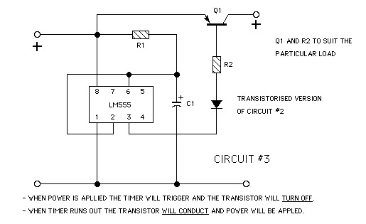
The goal is to create a small light that is activated by motion and stays illuminated for 20 seconds before turning off. For example, when the light is picked up, it illuminates, and when placed back down, it remains...
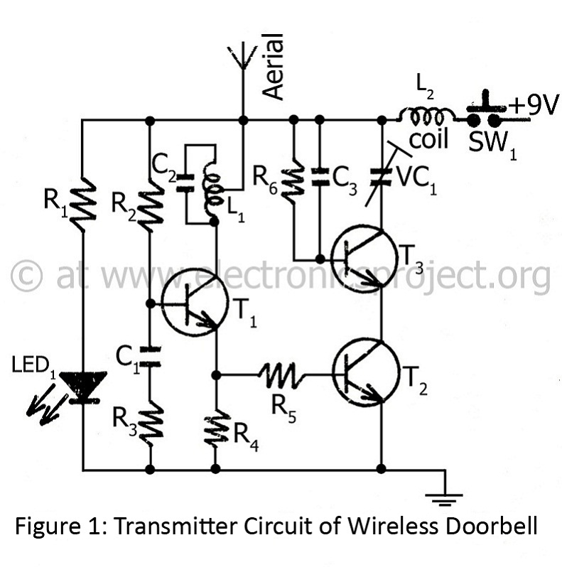
The controlling range of the wireless doorbell is 100 meters. The transmitter section is designed around an oscillator transistor (BF194B) T2, which is followed by two transistors (BC148) T1 and T3. Transistor T2 generates a specific radio frequency determined...
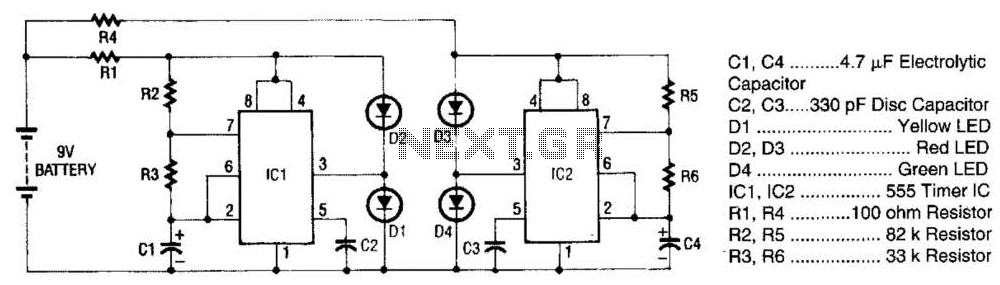
The super LED flasher consists of two complete LED flasher circuits integrated onto a single circuit board. The first LED flasher is comprised of IC1 and LEDs D1 and D2. IC1 is a 555 timer IC configured as an...
Efficient automatic solar garden lights circuit with minimal components. The advantage is that it operates completely automatically, with the solar panel serving as a light detector. The efficient automatic solar garden lights circuit is designed to provide illumination using renewable...
The Allegro A8732 is a Xenon photoflash charger integrated circuit (IC) specifically designed for ultra-low power, compact cameras, especially in mobile devices such as camera phones. It utilizes primary-side voltage sensing, which eliminates the need for a secondary-side resistive...
This article is about a software controlled, parallel port-interfacing 8-channel Pulse-Width-Modulated fan controller. I'll admit that the electronic part of it isn't very advanced, but hopefully the idea of "interfacing" might be interesting. My old partner and I were working...