
Wireless controlled Door-bell
The wireless doorbell circuit operates efficiently within a range of 100 meters, making it suitable for various residential applications. The transmitter section, centered around the BF194B transistor, is capable of generating a radio frequency that can be finely tuned using a variable capacitor and a coil. This tuning capability ensures optimal performance and reliable signal transmission.
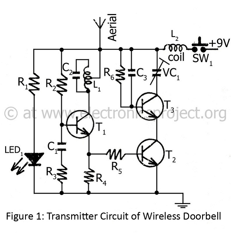
The pulse generation is handled by transistor T1, which creates the necessary pulse signals that modulate the carrier frequency produced by T2. The output from T3, acting as a buffer, provides a stable signal to T2's emitter, facilitating effective frequency generation. The use of trimmer VC1 allows for precise frequency adjustments, ensuring that the transmitter can operate without interference from other devices.
The receiver circuit, composed of seven transistors, is designed to capture the transmitted signal efficiently. Transistor T4 plays a crucial role in receiving the frequency from the hand unit and directing it to the tuned circuit, which consists of capacitor C6 and coil L2. This tuned circuit is essential for filtering out unwanted frequencies and ensuring that only the intended signal is processed.
Transistor T5 functions as a comparator, amplifying the received signal and coupling it to capacitor C11 for filtering. The filtered signal is then rectified in the detector stage, which prepares it for amplification. Transistor T6 amplifies the rectified signal, providing a stronger output that is necessary for driving subsequent stages.
The signal is then sent to transistor T7, which operates in complementary mode to control the conduction of transistors T8 and T9. The interaction between these transistors allows for the modulation of the output signal, ultimately enabling the sound generation through transistor T10. The blocking oscillator configuration of T10 is particularly effective for producing the desired bird sound, which is further enhanced by the output transformer.
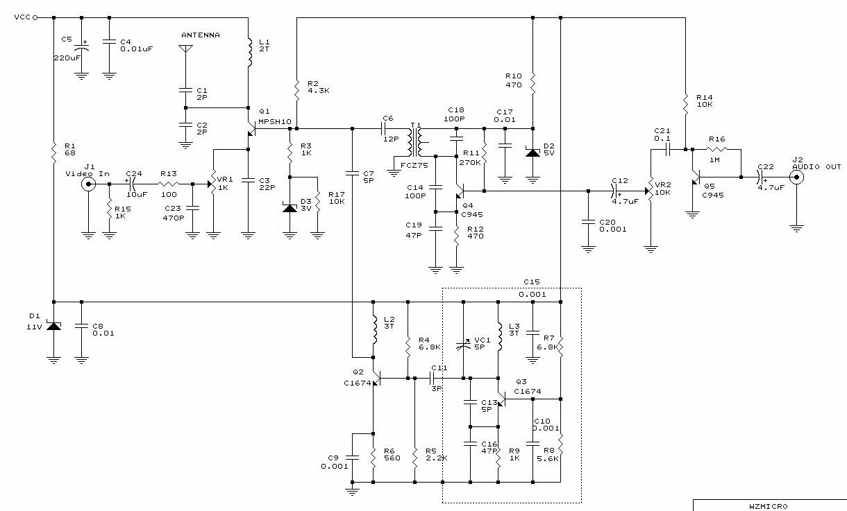
Overall, this wireless doorbell circuit exemplifies a well-designed system that integrates various electronic components to achieve reliable performance and sound generation. The careful selection and arrangement of transistors, along with tuning and filtering stages, contribute to the efficiency and effectiveness of the device.The controlling range of wireless doorbell is 100M. Transmitter:- This transmitter section is designed around oscillator transistor (BF194B) T2 followed by two transistor (BC148) T1 and T3. Transistor T2 generate special radio frequency determined by trimmer (variable capacitor) and coil. Transistor T1 is used as pulse generator. The output from transistor T3 is given to emitter of transistor T2 in order to get radio frequency from its collector. Trimmer VC1 is used to adjust the transmitter frequency. An aerial is used to receive the transmitted frequency from remote which is further amplified by amplifier and trigger circuit. The whole receiver circuit utilizes seven transistors. Transistor T4 get frequency from hand unit and further send to tuned circuit made from capacitor C6 and coil L2.
Transistor T5 is used as comparator which further send amplify voltage to capacitor C11 for filter. The filter voltage is passed through detector stage i. e. rectify and given to base of transistor T6. Transistor T6 is adjusted in amplifier mode for amplifying the signal voltage. The amplified voltage from transistor T6 is given to base of transistor T7, used in complementary mode. The positive voltage at collector of transistor T7 let transistor T8 in conducting state and T9 in non- conducting state.
The positive voltage available at collector of T9 is given to base of transistor T10. Transistor T10 is used here in blocking oscillator mode which further produces bird sound combining with output transformer. 🔗 External reference
Related Circuits
The NES version of this modification closely resembles the SNES version, and it is advisable to review that article first for a general understanding of the assembly of these controllers. The primary component required is an original NES controller,...
This circuit was featured in the "design ideas" section of EDN's March 5, 2007 issue. It is a relatively simple circuit that allows investigation into how the inductance of a toroid (or any core) is affected by saturation, which...
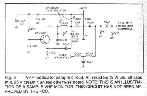
In this fast-paced world, there is little time for inconveniences and a greater need for portability and adaptability. The idea for an Audio/Video transmitter stems from this need. There may have been times when you’ve wanted to hook up...
This circuit enables wireless audio and visual transmission to a television, which serves as a receiver, thus negating the need for a separate monitor. Additionally, it can be connected to a VCR or CCD camera, facilitating the establishment of...
This circuit operates at 73 MHz and is designed for controlling halogen lights through radio frequency remote control. The primary function is to toggle the power state of a halogen lamp. When the button on the remote control is...
There is no prior experience in building controllers, and there is uncertainty about how to begin. A budget constraint of less than 100 euros is present. A power thyristor is already available. The inquiry revolves around the best method...