
LED signal amplifying circuit diagram
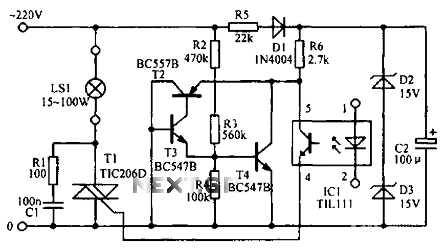
The LED signal amplification circuit is designed to enhance the output signal from an LED, allowing it to drive larger loads or to be interfaced with other electronic components effectively. The primary components of this circuit typically include an LED, a transistor, resistors, and capacitors.
In this configuration, the LED serves as the light source, which emits light when current flows through it. The transistor acts as a switch or amplifier, controlling the larger current that can be supplied to the load based on the input signal received from the LED. Resistors are used to limit the current flowing through the LED and to set the biasing conditions for the transistor, ensuring it operates within its safe limits. Capacitors may be included to filter noise and stabilize the circuit, ensuring smooth operation.
The circuit may be powered by a DC supply, and the output can be connected to various loads, such as additional LEDs, speakers, or other electronic devices. Proper design considerations, such as selecting the right transistor type (NPN or PNP), determining resistor values for biasing, and ensuring that the power supply voltage is compatible with the components, are crucial for achieving optimal performance and reliability of the LED signal amplification circuit. As shown in the circuit diagram for the LED signal amplification:
Related Circuits

This is a simple transmitter circuit diagram that offers decent coverage. The circuit can operate with a power supply of 9-12V. To tune this circuit... This simple transmitter circuit is designed to provide reliable performance within the specified voltage range....

This is a car alarm simulator that uses an LED as a simulation output. This simple circuit can indicate whether a car is running by detecting the voltage difference when the car is on and off. When the car...

The relay power in the linear circuit is derived from a -120 V bias supply, while the transmit keying output from the Kenwood device is +12 V with a maximum current of 10 mA. A critical component of this...
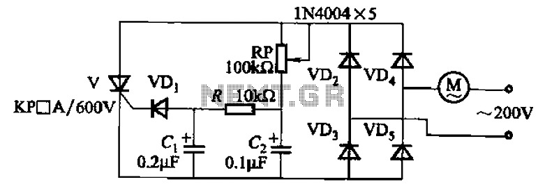
The circuit illustrated in Figure 3-11 employs a unidirectional thyristor control mechanism. An adjustable potentiometer, designated as RP, is utilized to continuously modify the motor speed. The circuit utilizes a unidirectional thyristor, also known as a silicon-controlled rectifier (SCR), which...
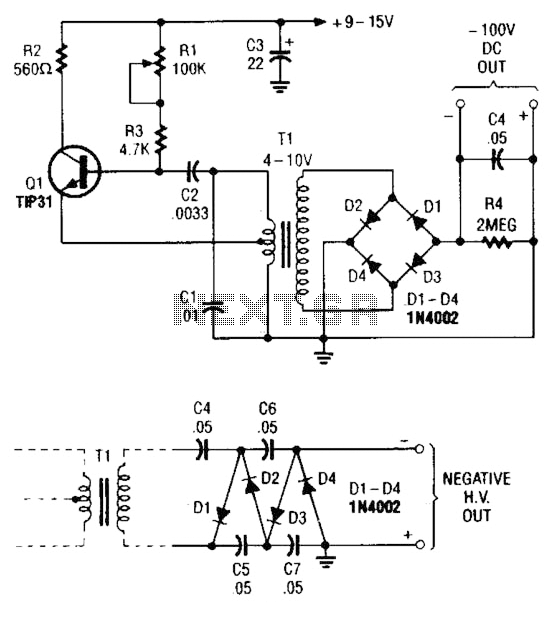
The combination of a Hartley oscillator and a step-up transformer can generate significant negative high voltage, particularly when the voltage output of the transformer is multiplied by the circuit. The Hartley oscillator is a type of LC oscillator that utilizes...

The touch delay switch, as illustrated in the figure, is composed of a CMOS NAND gate and is capable of providing a delay of approximately 10 seconds. It is commonly utilized for the automatic control of lighting in street...