
Single-phase motor stepless thyristor circuit 2
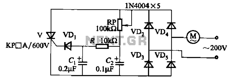
The circuit utilizes a unidirectional thyristor, also known as a silicon-controlled rectifier (SCR), which allows current to flow in one direction only. This characteristic is fundamental in controlling the power delivered to the motor. The thyristor is triggered into conduction by a gate signal, which can be controlled by the adjustment of the potentiometer RP.
The potentiometer RP is connected in such a way that its resistance can be varied, thereby altering the voltage applied to the gate of the thyristor. By adjusting RP, the phase angle at which the thyristor is triggered can be modified, leading to changes in the average voltage supplied to the motor. This results in a corresponding change in the motor's speed.
The circuit may also include additional components such as diodes for protection against reverse voltage, capacitors for filtering, and resistors to limit current. The configuration of these components is essential for ensuring stable operation and preventing damage to the thyristor and motor.
In practical applications, this type of circuit is often used in variable speed drives for DC motors, where precise control over speed is necessary for various industrial and automation tasks. The simplicity of the design combined with the effectiveness of the thyristor control makes it a popular choice in many electronic speed control applications. Circuit shown in Figure 3-11. It uses a one-way thyristor control. Adjustment potentiometer RP, continuously changing the motor speed.
Related Circuits
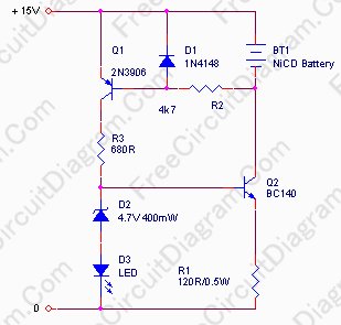
In appliances that require alternating current, NiCad (NiCd) rechargeable batteries still demonstrate significant performance advantages compared to NiMH and lithium batteries. The charger circuit is critical in handling incorrect polarity of the battery placement. The core of this battery...
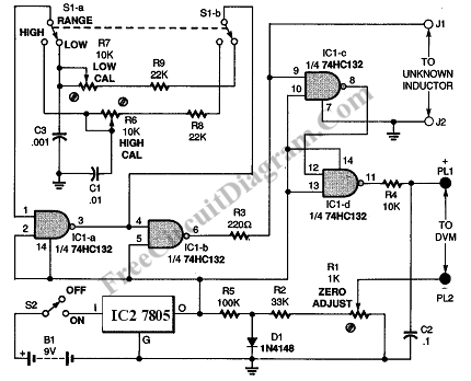
This inductance meter serves as an adapter for a digital voltmeter (DVM), enabling the voltmeter to measure the value of inductors. The inductance meter is particularly useful in designing switch mode power supplies, as it often requires hand-winding coils...

The circuit diagram for the receiving portion of a 2.4 GHz wireless keyboard is presented below. The 2.4 GHz wireless keyboard receiving circuit typically consists of several key components that work together to receive and process signals transmitted from the...

When an alarm or notification is needed after ten minutes, the circuit illustrated below can be utilized. This circuit is essentially a monostable multivibrator based on the IC NE555. When the reset push button is pressed, the green LED...

This design outlines a fire alarm circuit that utilizes a light-dependent resistor (LDR) and a lamp to detect fire. The alarm is activated by sensing the smoke produced during a fire. When smoke is present, it obstructs light from...
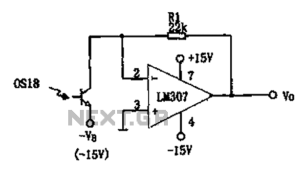
The circuit described is a photoelectric receiver amplifier designed to amplify the electrical signals generated by photodiodes or phototransistors in optoelectronic devices. When the intensity of incident light varies, the photosensitive device generates a corresponding voltage or current. The...
Warning: include(partials/cookie-banner.php): Failed to open stream: Permission denied in /var/www/html/nextgr/view-circuit.php on line 713
Warning: include(): Failed opening 'partials/cookie-banner.php' for inclusion (include_path='.:/usr/share/php') in /var/www/html/nextgr/view-circuit.php on line 713