
led thermometer pcb

The circuit described is a versatile LED display circuit capable of operating in two modes: dot mode and graph mode, depending on the configuration of pin 9 of operational amplifier U2. The choice of LEDs (D1 - D10) is flexible, though it is important to consider the voltage requirements of the selected LED colors. Blue LEDs, while aesthetically modern, may not provide the same brightness as their red, yellow, or green counterparts due to their higher forward voltage.
In dot mode, with pin 9 disconnected, a resistor value of 100 Ohms for R8 is specified, which allows for optimal current flow through the LEDs without exceeding their ratings. Conversely, when pin 9 is connected to a 9V supply, the circuit transitions to graph mode, necessitating a lower resistance value of 15 Ohms for R8 to accommodate the increased current flow required for this mode.
Calibration of the circuit is a critical step to ensure accurate voltage readings. This process begins with powering the circuit and allowing it to stabilize thermally, which is essential for achieving consistent measurements. The use of a voltmeter is integral to this process. By grounding the negative lead and connecting the positive lead to pins 6 and 7 of U2, R7 can be adjusted to achieve a target voltage of 3.345V. This step ensures that the operational amplifier is functioning within its specified parameters.
Subsequently, the positive lead is moved to pin 4 of U2, where R5 is adjusted to yield a reading of 2.545V. This calibration step is crucial for ensuring that the output of the operational amplifier aligns with the desired performance characteristics of the circuit.
After completing the calibration, the circuit must be powered down to safely remove U1 and U2 from their sockets for further adjustments. The resistance of R3 is measured with an ohmmeter, and this value is used to set R1 to three times the value of R3, ensuring that the circuit maintains proper scaling and functionality. Once these adjustments are made, U1 and U2 are reinstalled, and the circuit is prepared for use, ready to provide visual feedback through the LED display in either mode.You can use any LED you want for D1 - D10, however blue LEDs have a higher voltage requirement so if you want to go blue for a modern look, they may appear more dim then red, yellow or green. By leaving pin 9 of U2 disconnected, the graph will operate in dot mode and R8 should be 100 Ohm. If you build the circuit with pin 9 tied to 9V, the circuit will be in graph mode and R8 should be 15 Ohms. To calibrate the circuit, you will need a voltmeter. Power the circuit up and let it sit for a few minutes for temperature to stabilize. Ground the negative lead of the meter and connect the positive lead to pins 6 and 7 of U2. Set R7 so the meter reads as close to 3. 345V as possible. Now connect the positive lead of the meter to pin 4 of U2 and adjust R5 until the meter reads 2. 545V. Finally, disconnect power to the circuit and remove U1 and U2 from their sockets. Measure the value of R3 with an ohmmeter and remember that value. Connect the ohmmeter across R1 and adjust R1 to a value of exactly 3 times the value of R3. Reinstall U1 and U2 and the circuit is ready for use. 🔗 External reference
Related Circuits
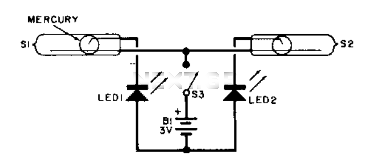
This electronic level utilizes two LED indicators in place of an air bubble. When the surface tilts to the right, one LED illuminates; conversely, if it tilts to the left, the other LED illuminates. Both LEDs light up when...
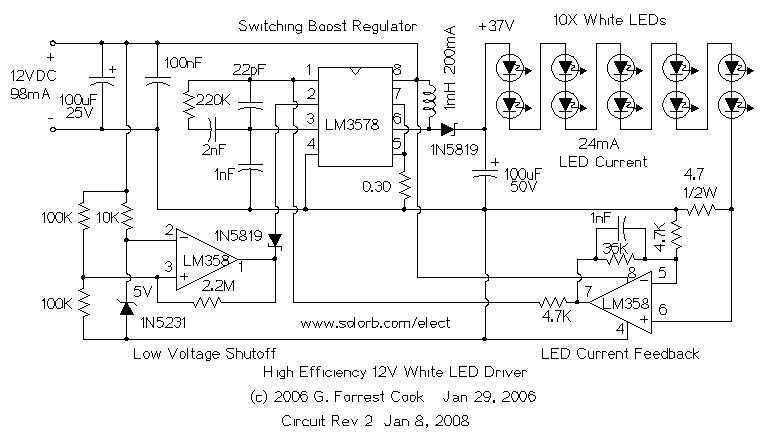
The heart of the circuit is a string of 10 white LEDs. These are wired in series and connected to a current-regulated step-up switching power supply circuit. DC powered LED lighting circuits can vary from the trivial, with a...
The bi-directional sequencer employs a 4-bit binary up/down counter (CD4516) and two "1 of 8 line decoders" (74HC138 or 74HCT138) to create the well-known "Night Rider" display. A Schmitt Trigger oscillator generates the clock signal for the counter, with...
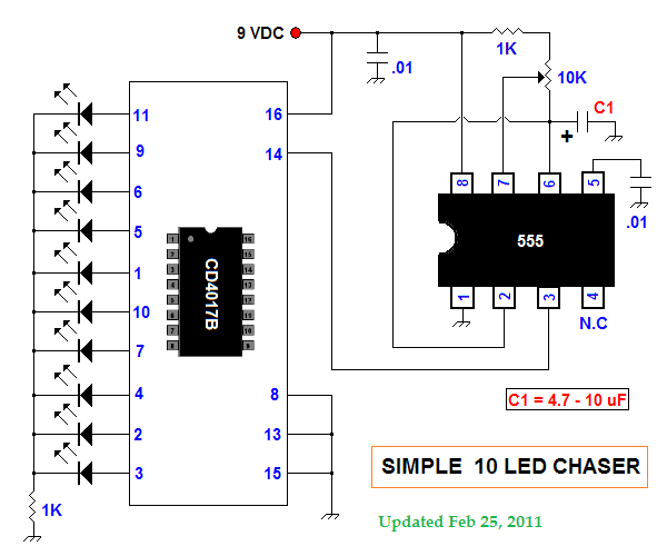
This summer, several LED projects were constructed, including sequential LED chasers that operate from left to right and a Nite-Rider style that moves sequentially left, right, left, right, and so on. These projects are enjoyable for children to experiment...
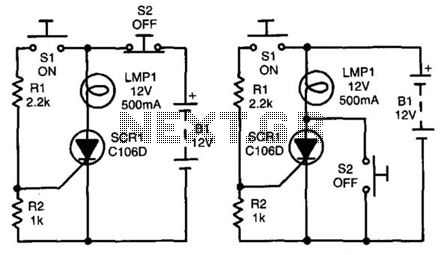
In both circuits, the SCR (Silicon Controlled Rectifier) and the lamp can be latched on by momentarily closing switch S1, which provides gate drive to the SCR through resistor R1. In both configurations, the gate is connected to the...

This sign design does not utilize a microprocessor. Instead, it employs an EPROM and multiple counters. Similar to most electronic signs, the LEDs are arranged in a matrix and are stroboscopically activated at a high frequency to create the...