
LED Voltage indicator
The described circuit is a simple voltage comparator using an operational amplifier (op-amp) configured in a non-inverting mode. The primary function of this circuit is to control an LED based on the input voltage level relative to a reference voltage set by a variable resistor (R2).
In this configuration, the input voltage is applied to the non-inverting terminal of the op-amp (U1, UA741). The inverting terminal is connected to a voltage divider formed by R1 and R2, where R2 is a variable resistor that allows for fine-tuning of the reference voltage. When the input voltage is at 0V, the output of the op-amp is high, which turns on the LED (D1). As the input voltage increases, it will eventually reach a threshold determined by the voltage at the inverting terminal. When the input voltage exceeds this threshold, the output of the op-amp goes low, turning off the LED.
To reverse the operating mode, the + and - pins of the op-amp can be swapped, which will invert the logic of the LED's operation. This means that the LED will glow when the input voltage exceeds the reference voltage set by R2 and will turn off when the input voltage is below this threshold.
To set the voltage level at which the LED turns off, the following steps should be followed:
1. Ensure that the input voltage is set to 0V.
2. Gradually increase the input voltage to the desired level.
3. Adjust R2 until the LED just turns off, indicating that the input voltage has reached the set threshold.
The components used in this circuit include:
- D1: An LED that serves as the output indicator.
- R1: A fixed resistor of 1.2kΩ that helps set the voltage divider.
- R2: A variable resistor of 10kΩ that allows for adjustable reference voltage.
- U1: A UA741 operational amplifier, which serves as the core component for voltage comparison.
This circuit can be utilized in various applications where visual indication of voltage levels is required, such as in battery level indicators, signal level detectors, or simple alarm systems.When the input voltage is 0 the LED glows. The LED stops glowing when the voltage rises to the level determined by R2. Reverse + and - pins to reverse operating mode. To set voltage at which LED goes off, (1) Set 0V at input. (2) Set input voltage at desired level. (3) Adjust R2 to point right after LED goes out. Parts List D1 LED R1 1.2k Resistor R2 10k Var. Resistor U1 UA741 OP AMP 🔗 External reference
Related Circuits
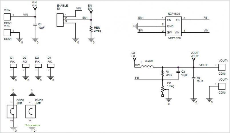
The LinkSwitch-XT LNK363DN-based flyback power supply generates a single isolated DC output voltage from an input voltage range of 90 VAC to 264 VAC. The power supply delivers an output of 5 V at 550 mA (2.75 W) in...
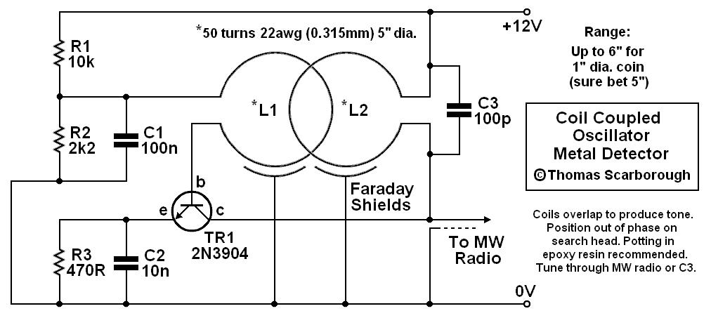
A coil-coupled operation metal detector constructed from commonly available components, utilizing a standard medium receiver as the detection unit. The coil-coupled operation metal detector functions by employing a transmitter coil and a receiver coil that are magnetically coupled. The transmitter...
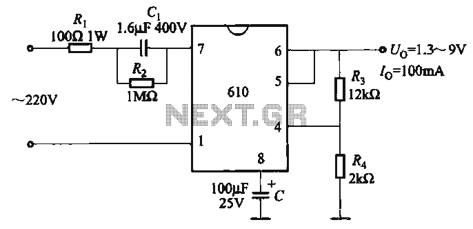
The output voltage can be calculated as follows: U = 1.3 (1 + R3 / R4) (V), where R3 and R4 are part of an adjustment potentiometer, allowing for a continuously adjustable output voltage. The described circuit involves a voltage...

This single-chip circuit adjusts its audio gain according to the ambient noise picked up by the microphone. When operating in a quiet environment, the audio output is quiet, while a noisy environment results in a louder audio output. Audio...
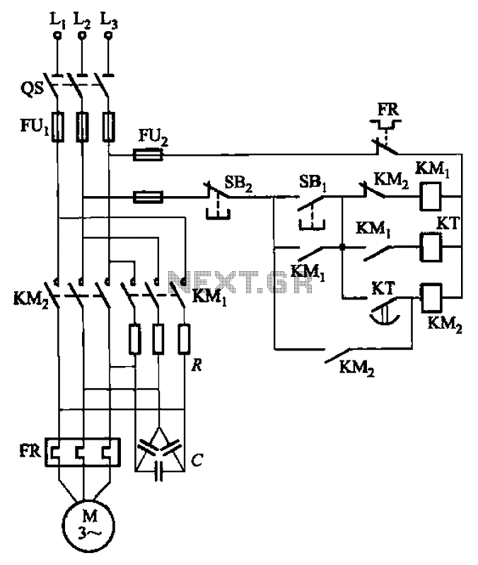
The circuit depicted in Figure 3-35 demonstrates a method for starting a motor that transitions to full voltage through a step-down switching process. This approach provides an uninterruptible power supply, effectively preventing issues related to switching currents that may...
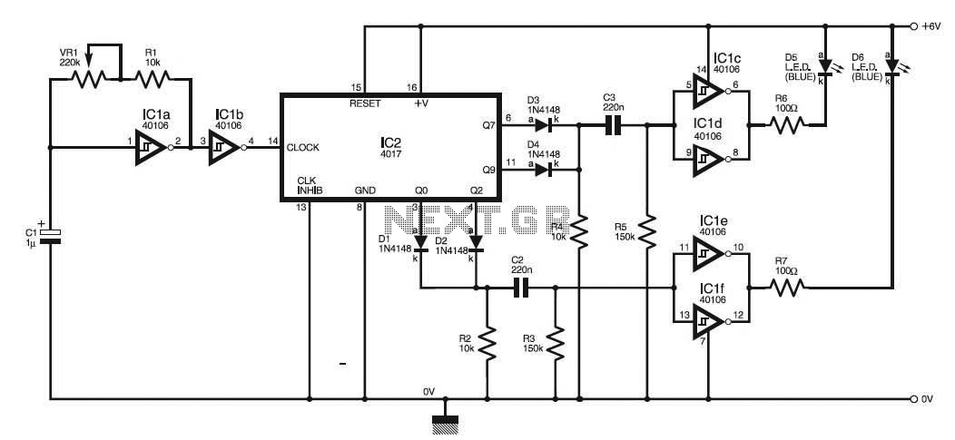
This circuit simulates the flashing strobe lights of British police cars by alternating the lights. The IC1a functions as a square wave oscillator with an adjustable frequency controlled by VR1 to achieve the desired effect. The circuit utilizes an...