
LED voltmeter schematic needed
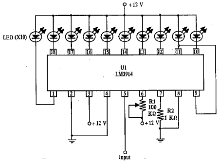
The proposed LED voltmeter circuit utilizes a series of light-emitting diodes (LEDs) to visually represent the voltage level of a variable power supply. This circuit can be designed using a voltage divider, an operational amplifier, and a set of LEDs calibrated to indicate specific voltage ranges.
To begin, a voltage divider composed of two resistors (R1 and R2) is connected across the variable power supply. The output voltage from the voltage divider is proportional to the input voltage and can be calculated using the formula Vout = Vin * (R2 / (R1 + R2)). This output voltage is then fed into the non-inverting input of an operational amplifier (Op-Amp), which is configured for voltage comparison.
The Op-Amp is set up with a reference voltage that corresponds to specific voltage thresholds. For instance, if monitoring a supply voltage ranging from 0 to 12 volts, the Op-Amp can be configured to switch states at intervals such as 2V, 4V, 6V, 8V, 10V, and 12V. Each output from the Op-Amp can control a corresponding LED. When the voltage exceeds a certain threshold, the Op-Amp output will go high, turning on the associated LED.
To enhance the circuit's functionality, a resistor can be placed in series with each LED to limit the current and prevent damage. Additionally, a potentiometer can be included in the voltage divider to allow for calibration of the circuit, ensuring accurate voltage readings.
The final output will be a series of lit LEDs, each representing a specific voltage level, providing a clear and immediate visual indication of the variable supply's voltage. This LED voltmeter circuit is not only simple to construct but also effective for real-time voltage monitoring in various applications.Hello, I need a simple to make LED based (not 7-segment) voltmeter to monitor the voltage of a variable supply. I have found this circuit.. 🔗 External reference
Related Circuits
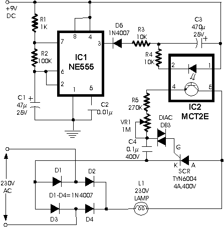
This circuit can be used to construct an attractive Christmas Star. When we switch on this circuit, the brightness of lamp L1 gradually increases. When it reaches the maximum brightness level, the brightness starts decreasing gradually. And when it...
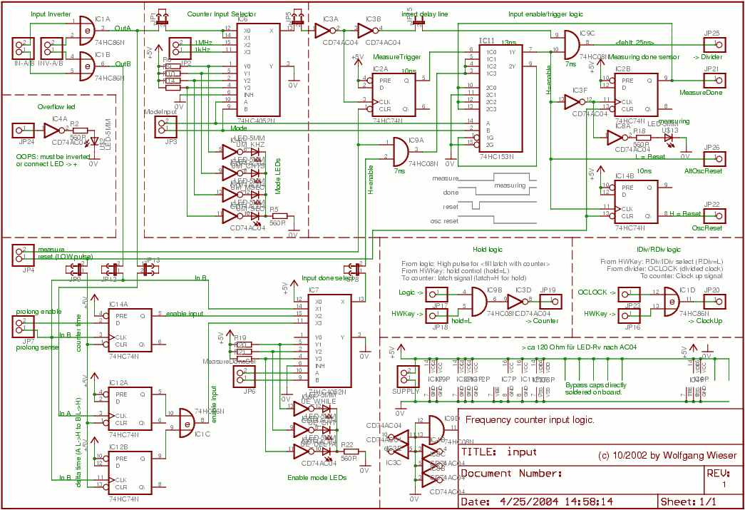
The master mode selection switch is IC6, which controls the four mode LEDs that correspond to the measured units: kHz, counts, milliseconds, or seconds. In standard frequency counter mode (mode 0, unit: kHz) and counter mode (mode 1, unit:...
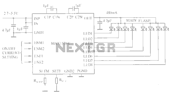
The circuit utilizes the MAX1576Y charge pump white LED driver, capable of supplying a total current of up to 480mA across two groups (n = 4 white LEDs). Each white LED in the flashing group can draw a maximum...
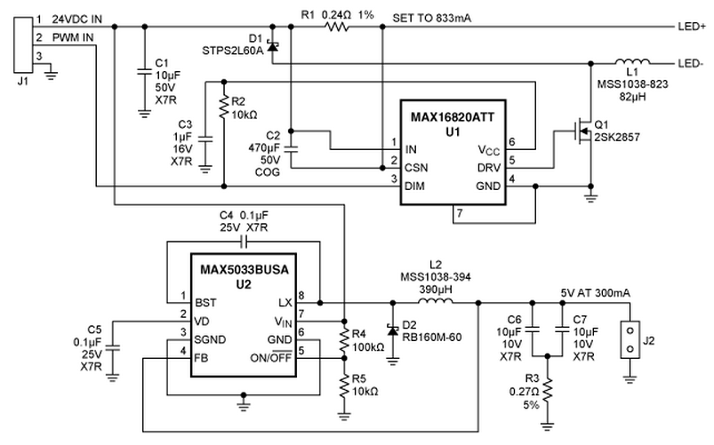
A reference design for a 4S1P MR-16 LED driver that provides 750mA to a string of four white LEDs (WLEDs). The circuit operates from a 24V source and is based around the MAX16820 hysteretic LED driver. Also included is...
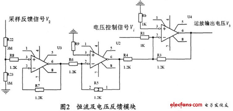
The output current range of the parameter current regulator is limited, and its precision is not high. Connecting the feedback adjustment type output current of the current-stabilized power source in series results in lower efficiency. The steady current source...
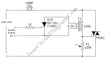
This is an audio-controlled lamp circuit. This circuit requires a low voltage input, such as from pre-amplifiers, tone control, or general audio line level output. The audio-controlled lamp circuit is designed to activate a lamp in response to audio signals....