
LED Christmas Star

This circuit design centers around an astable multivibrator configuration using an integrated circuit (IC1), which generates a square wave output. The frequency of this oscillation can be adjusted by modifying the values of resistor R2 and capacitor C1. The output from IC1 controls the charging and discharging of capacitor C3, which in turn modulates the brightness of lamp L1. As the capacitor charges, the brightness of L1 increases, and as it discharges, the brightness decreases, creating a smooth fading effect.
The inclusion of an opto-isolator (IC2) ensures electrical isolation between the control circuit and the lamp circuit, enhancing safety and reducing the risk of electrical shock. The brightness control is further refined by the potentiometer VR1, which allows for adjustment of the minimum brightness level of the lamp. This feature is crucial for achieving the desired visual effect, especially in varying supply voltage conditions.
Resistors R3 and R4 play a significant role in stabilizing the circuit's performance when the frequency of IC1 is altered. It is essential to adjust these resistors in accordance with any changes made to R2 or C1 to maintain optimal functionality.
Care must be exercised when adjusting VR1, as improper settings can lead to flickering or prolonged off states of the lamp. If the brightness remains excessively high, increasing the resistance of VR1 will help achieve a more balanced output. Conversely, if the resistance is too high, the lamp may not reach the desired brightness levels.
For switching applications, a triac like the BT136 can replace the SCR, providing robust control over the lamp's operation. Proper precautions should be taken to ensure safe handling of the circuit, particularly when making adjustments to the potentiometer VR1, due to the potential risk of electrical shock.This circuit can be used to construct an attractive Christmas Star. When we switch on this circuit, the brightness of lamp L1 gradually increases. When it reaches the maximum brightness level, the brightness starts decreasing gradually. And when it reaches the minimum brightness level, it again increases automatically. This cycle repeats. The increase and decrease of brightness of bulb L1 depends on the charging and discharging of capacitor C3. When the output of IC1 is high, capacitor C3 starts discharging and consequently the brightness of lamp L1 decreases.
IC2 is an opto-isolator whereas IC1 is configured as an astable multivibrator. The frequency of IC1 can be changed by varying the value of resistor R2 or the value of capacitor C1. Remember that when you vary the frequency of IC1, you should also vary the values of resistors R3 and R4 correspondingly for better performance. The minimum brightness level of lamp L1 can be changed by adjusting potentiometer VR1. If the brightness of the lamp L1 does not reach a reasonable brightness level, or if the lamp seems to remain in maximum brightness level (watch for a minute), increase the in-circuit resistance of potmeter VR1.
If in-circuit resistance of potmeter VR1 is too high, the lamp may flicker in its minimum brightness region, or the lamp may remain in off state for a long time. In such cases, decrease the resistance of potmeter VR1 till the brightness of lamp L1 smoothly increases and decreases.
When supply voltage varies, you have to adjust potmeter VR1 as stated above, for proper performance of the circuit. A triac such as BT136 can be used in place of the SCR in this circuit. Caution: While adjusting potmeter VR1, care should be taken to avoid electrical shock. 🔗 External reference
Related Circuits

The voltage to be measured is digitized in an analog-to-digital (A/D) converter and then displayed in three decimal digits. The display consists of three groups of 10 LEDs. The meter can only be used for measuring direct voltages. The...
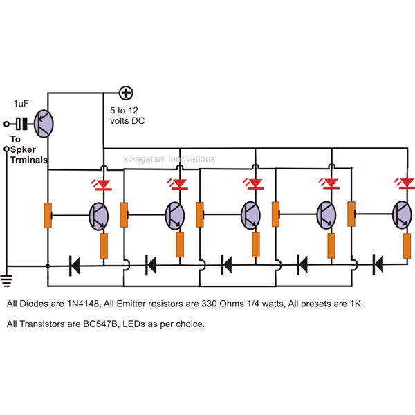
The LEDs in the circuit light up sequentially and "dance" in response to the music level applied at the input, preferably from the speaker terminals of the audio device being monitored. This configuration is consistent across all LEDs in...

When discussing fan control, there are generally two methods: linear control and pulse-width modulation (PWM) control. Linear control is the most commonly used method, which involves reducing the voltage supplied to the fan. For a fan rated at 12...
This circuit is used to power an LED with a voltage of 230V. The 230V must be reduced to meet the LED's voltage requirements. To achieve this, a circuit is necessary as described below. The circuit designed to power an...
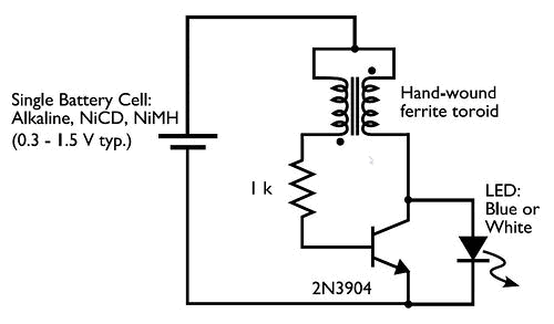
Concerned about darkness? Constructed a basic Joule Thief circuit and wish to advance further? Seeking a striking blue light to impress friends? Introducing the Joule Thief 10x10 LED Lamp! This device operates on one to four AA batteries and...
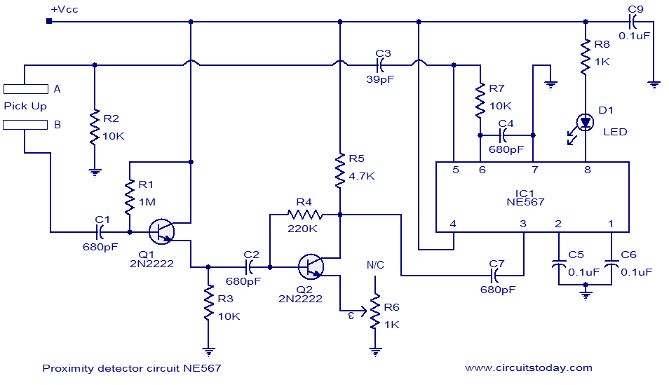
A simple proximity detector circuit utilizing the NE567 integrated circuit (IC). The circuit activates an LED when an object approaches the sensor. The NE567 is a versatile phase-locked loop (PLL) device commonly used for applications such as proximity detection due...