
LED VU Meter by IC LM3914 PCB

The LED VU Meter circuit operates by taking an audio input signal and converting it into a visual output using a series of light-emitting diodes (LEDs). The LM3914 is a versatile integrated circuit that can drive up to 10 LEDs, allowing for a clear indication of the audio signal's amplitude. The circuit can be configured to operate in either bar graph or dot mode, depending on the desired visual effect.
To construct the circuit, the LM3914 is connected to a resistor ladder that sets the reference voltage levels for the LEDs. The input audio signal is fed into the IC, which processes the signal and lights up the corresponding number of LEDs based on the signal's strength. Typically, the circuit requires a power supply of 12V, and the LEDs are connected in parallel with current-limiting resistors to prevent damage.
Additional components may include capacitors for filtering noise from the audio signal and potentiometers for adjusting the sensitivity of the meter. A suitable enclosure can be used to house the circuit and provide a professional appearance. The circuit can be further enhanced by adding features such as backlighting for the LEDs or integrating it with a microcontroller for advanced audio visualization capabilities.
This LED VU Meter is an excellent project for audio enthusiasts and engineers, providing a practical application of the LM3914 IC while enhancing understanding of audio signal processing and visual representation.This be LED VU Meter by IC LM3914 circuit show with LED convenient for the stereo or sound all signal. This easy circuit again because use IC LM3914 show get 10 the level. Build easy because use the integrated circuit just one and the price is inexpensive. The detail is all, see in the circuit better. 🔗 External reference
Related Circuits
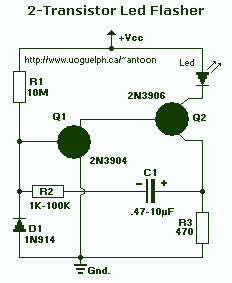
This circuit will flash a super-bright LED (5000+ mcd). Good for fake car alarm or other attention-getting device. Component values are not critical; try anything else first from your junk box. Obviously, the 470 ohm resistor (R3) determines the...
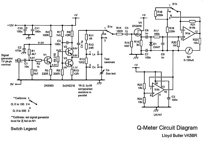
The Q meter has been an essential piece of equipment for laboratories engaged in the testing of radio frequency circuits. In modern laboratories, the Q meter has been largely replaced by more advanced and costly impedance measuring devices, making...
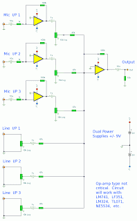
The mixer circuit features three line inputs and three microphone inputs. The microphone inputs are designed to accommodate low impedance dynamic microphones with an impedance range of 200 to 1000 ohms. An electret condenser microphone (ECM) can also be...
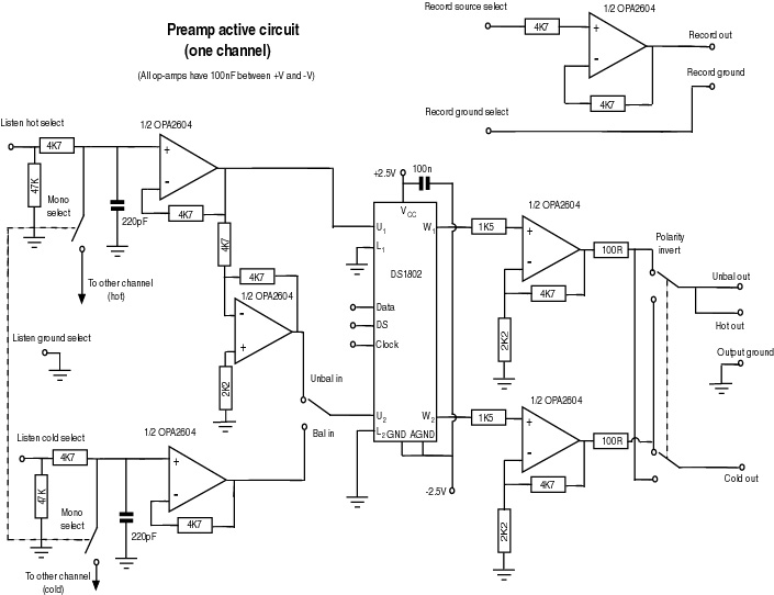
This document serves as a compilation of design notes, providing practical details as construction progresses, along with some photographs that will be included in due course. Currently, it functions as a progress report, blending immediate plans with actual construction,...
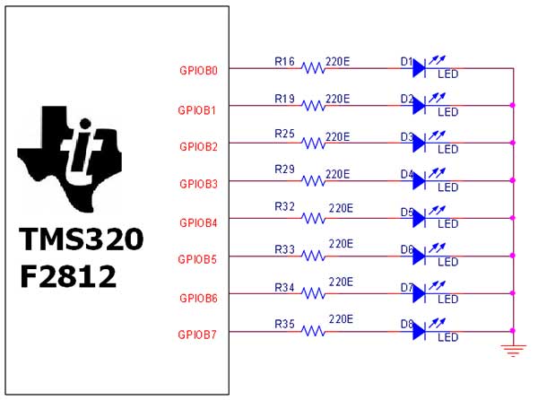
The TMS320F2812 Evaluation Board is specifically designed for developers in the digital signal processing (DSP) field, as well as for beginners. The F2812 kit is structured to allow easy access to all the features of the DSP. The TMS320F2812...
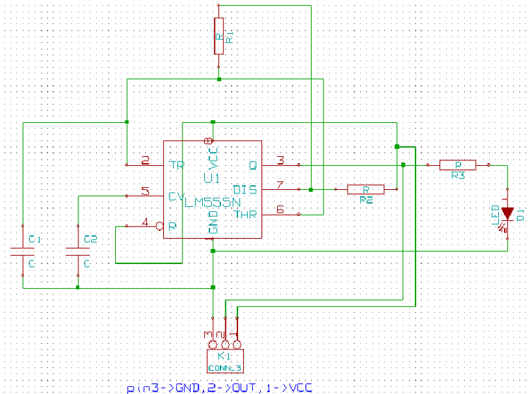
This is a brief guide to help users begin with KiCAD. The tutorial focuses on a simple astable multivibrator circuit utilizing the 555 timer IC. The astable multivibrator circuit using the 555 timer IC is a fundamental electronic configuration that...