
Led light based music circuit with LM3914

The described circuit utilizes a basic audio input to control a light display, creating a visual effect that responds to the rhythm and intensity of the music. The circuit typically includes a microphone or audio input jack to capture sound from a music source, such as a CD player.
Key components of the circuit include an operational amplifier (op-amp) configured as a comparator, which processes the audio signal. The output from the op-amp can drive a transistor or a MOSFET, which in turn controls the power to the light source, such as LEDs or incandescent bulbs.
The circuit may also incorporate a resistor-capacitor (RC) filter to smooth out the audio signal, ensuring that the lights respond accurately to the desired frequencies. A potentiometer can be included to adjust the sensitivity of the circuit, allowing the user to set how responsive the lights are to the music volume.
For safety and performance, it is advisable to use a power supply that matches the specifications of the light source. Additionally, appropriate heat sinks should be used for the transistor or MOSFET if high power levels are involved.
Overall, this simple light-running circuit provides an engaging way to visualize music and can be easily assembled with minimal electronic knowledge.This is a simple light running circuit by music This circuit is not difficult, is MONO, with a few accessories. Can be connected to the output of a CD or. 🔗 External reference
Related Circuits
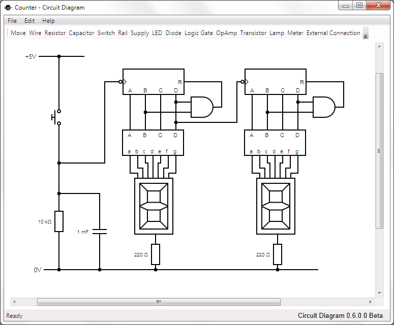
This is Circuit Diagram 0.1 Alpha Software, available for free download and open source. The Circuit Diagram 0.1 Alpha Software is designed as an intuitive platform for creating and editing electronic circuit schematics. It provides users with a variety of...
This is a remote tester circuit designed to test TV and other remote controls. The circuit is simple and utilizes only a few components. The infrared sensor used in the circuit is the TSOP1738. When the infrared waves are...
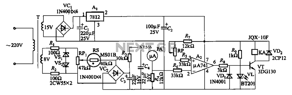
The humidity alarm system is based on integrated circuits and relays, utilizing the pA741 circuit. The MS01 employs a wet-type humidity resistance element as a probe. When the humidity exceeds a predetermined value, specifically set at 6 feet high,...
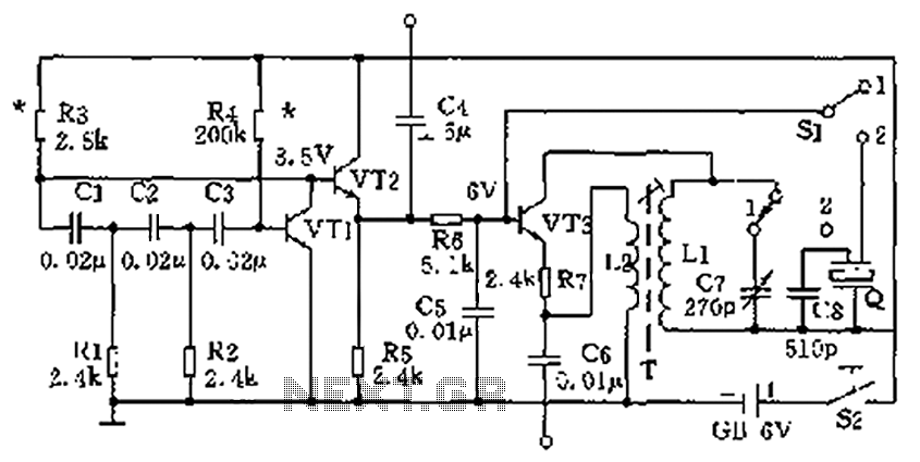
The high-frequency signal generator is designed to produce a low frequency of 1 kHz, an intermediate frequency (IF) signal of 465 kHz, and high frequencies ranging from 525 kHz to 1605 kHz. This device is particularly useful for radio...
This is a resonant mode LED driver circuit. This circuit is designed to provide a constant DC current through a specified number of LEDs. The resonant mode LED driver circuit operates by utilizing resonant inductive elements to achieve efficient energy...
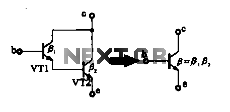
There are two composite pipe configurations: one consists of two transistors of the same type, while the other is made up of two different types of pipe configurations. The first configuration, utilizing two transistors of the same type, typically involves...