
LEDs and Switches

The DE2 board is designed to facilitate various input and output operations through its integrated components. The four debounced pushbutton switches utilize Schmitt Trigger circuits to provide stable and reliable transitions between logic levels, mitigating the effects of mechanical bounce that can occur during switch actuation. This feature enhances the performance of the switches when used for critical functions such as clock signals or reset inputs in digital circuits.
The connection of the switches to the Cyclone II FPGA allows for seamless integration into digital designs, enabling the FPGA to read the status of each switch accurately. The toggle switches, while lacking debouncing, serve as effective level-sensitive inputs, providing a straightforward method for users to interact with the FPGA. The clear logic level outputs from the toggle switches make them suitable for applications where continuous monitoring of the switch state is necessary.
The presence of 27 user-controllable LEDs offers visual feedback for the operation of the circuit. The arrangement of red and green LEDs allows for differentiated signaling, where red LEDs can indicate specific states or statuses of the toggle switches, while green LEDs can provide feedback from the pushbutton switches. The direct connection of the LEDs to the Cyclone II FPGA ensures that the control over these indicators is straightforward and flexible, allowing for dynamic updates based on the logic implemented within the FPGA.
Overall, the DE2 board's design, with its combination of debounced pushbutton switches, toggle switches, and user-controllable LEDs, provides a robust platform for developing and testing digital circuits, making it an invaluable resource for electronics engineers and hobbyists alike. The accompanying schematic diagrams further enhance understanding by visually representing the connections and functionalities of these components.The DE2 board provides four pushbutton switches. Each of these switches is debounced using a Schmitt Trigger circuit, as indicated in Figure 1. The four outputs called KEY0, . , KEY3 of the Schmitt Trigger device are connected directly to the Cyclone II FPGA. Each switch provides a high logic level (3. 3 volts) when it is not pressed, and provides a low logic level (0 volts) when depressed. Since the pushbutton switches are debounced, they are appropriate for use as clock or reset inputs in a circuit. There are also 18 toggle switches (sliders) on the DE2 board. These switches are not debounced, and are intended for use as level-sensitive data inputs to a circuit.
Each switch is connected directly to a pin on the Cyclone II FPGA. When a switch is in the DOWN position (closest to the edge of the board) it provides a low logic level (0 volts) to the FPGA, and when the switch is in the UP position it provides a high logic level (3. 3 volts). There are 27 user-controllable LEDs on the DE2 board. Eighteen red LEDs are situated above the 18 toggle switches, and eight green LEDs are found above the pushbutton switches (the 9th green LED is in the middle of the 7-segment displays).
Each LED is driven directly by a pin on the Cyclone II FPGA; driving its associated pin to a high logic level turns the LED on, and driving the pin low turns it off. A schematic diagram that shows the pushbutton and toggle switches is given in Figure 2. A schematic diagram that shows the LED circuitry appears in Figure 3. 🔗 External reference
Related Circuits
The circuit is a 0-60 second timer using timer 555 and two 4017 for LED driving. The described circuit employs a 555 timer IC configured in monostable mode to create a timing interval ranging from 0 to 60 seconds. The...

This transistor has only one IC tester and can test all types of transistors. With two LEDs indicating the type of the transistor is NPN or PNP. The circuit uses a CMOS 4049 IC. The test transistor to terminals...
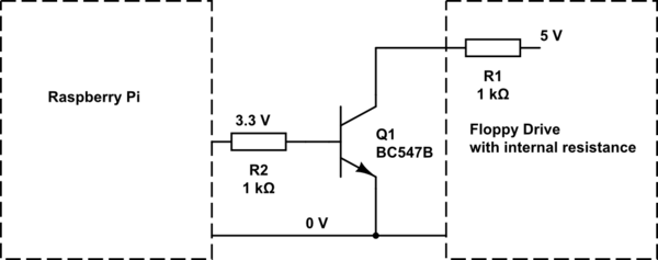
Experiments with a couple of floppy drives indicate that the current on the step pin is limited to approximately 5 mA. This allows for the omission of the collector resistor in this scenario. A base resistor of 1 kiloohm...

A dimming control circuit generates a dimming control signal to determine the brightness of at least one light-emitting diode. The dimming control signal consists of multiple bright-dark cycles, each comprising a bright phase and a dark phase. The bright...
This LED flasher circuit utilizes a 555 integrated circuit (IC) and is designed to drive multiple LEDs. Notably, connecting several LEDs in series does not increase the power consumption. The LED flasher circuit based on the 555 timer IC is...
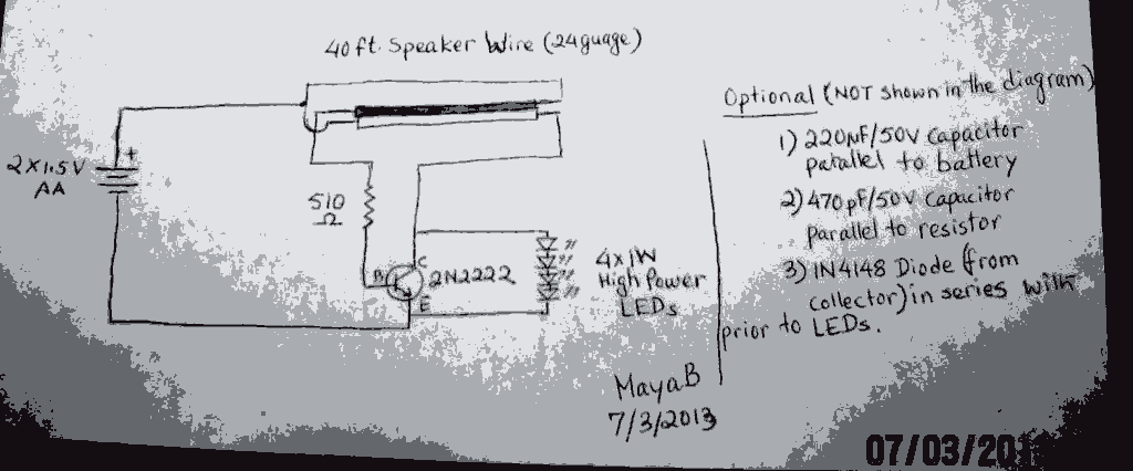
The post discusses a Joule Thief circuit that drives and illuminates four 1-watt LEDs using a single 1.5V pencil cell. The Joule Thief circuit is a minimalist boost converter designed to extract energy from low-voltage power sources, such as a...