LEDs Fade In/Out Circuit Problem and LED Sequencer

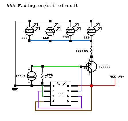
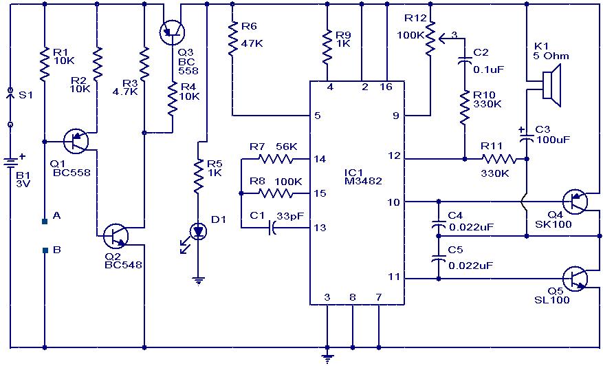
A circuit was constructed based on an LED beating heart frame instructable, but it is not functioning as expected. There is also mention of a built LED sequencer.
The LED beating heart circuit typically involves a microcontroller, such as an Arduino, which controls a series of LEDs to create a pulsating effect that mimics a heartbeat. The circuit may include components such as resistors, capacitors, and transistors to manage the current flow and timing of the LED activation. Commonly, the microcontroller is programmed to turn the LEDs on and off in a specific sequence, creating the desired visual effect.
To troubleshoot the circuit, it is essential to verify the connections and ensure that all components are correctly placed according to the schematic. Checking the power supply for the correct voltage and ensuring that the microcontroller is properly programmed are also critical steps. If the circuit includes a sequencer, it may be beneficial to test it independently to confirm its functionality before integrating it with the heart circuit.
In the schematic, the microcontroller is usually connected to the LEDs through transistors, which act as switches to handle the higher current required by the LEDs. Resistors are used in series with the LEDs to limit the current and prevent damage. Capacitors may be included to stabilize the power supply and filter out noise.
In conclusion, careful examination of the circuit layout, component specifications, and programming code is essential for diagnosing and resolving the issues encountered with the LED beating heart frame and sequencer circuits.I built this circuit from the led beating heart frame instructable. I can`t seem to get it to work. Any ideas? I also built this led sequencer. It doe.. 🔗 External reference


