
Auto ON-OFF lights
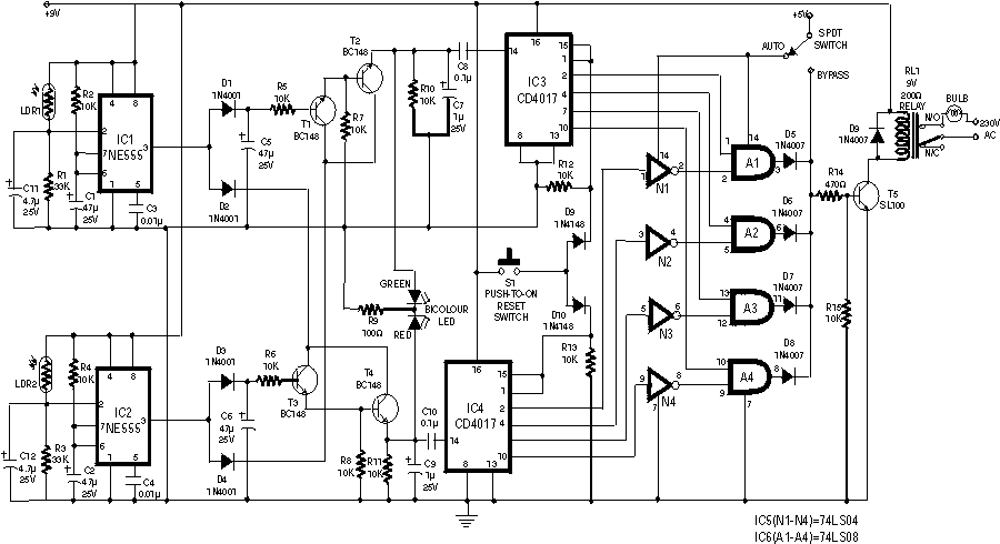
The automatic room power control circuit described utilizes a dual light-dependent resistor (LDR) setup to effectively manage the lighting within a room based on the presence of individuals. The LDRs are strategically positioned approximately half a meter apart to allow for sequential detection of individuals entering or exiting the room. This dual-sensor configuration mitigates the issue of simultaneous entries, which could result in the lights remaining off due to multiple pulses being sent to the control circuit.
Upon entering the room, the first LDR (LDR1) is obstructed, triggering the first monostable flip-flop (IC1) configured with a timer function. The output pulse from IC1 initiates a series of actions, including charging a capacitor (C5) that subsequently activates a transistor pair (T1 and T2). This action briefly illuminates the green segment of a bi-colour LED, indicating entry. The output from IC1 also serves as a clock pulse to a counter IC (IC3), which tracks the number of entries.
When a person exits, the second LDR (LDR2) is triggered first, activating the second monostable flip-flop (IC2). This flip-flop performs a similar function as IC1 but in reverse, illuminating the red segment of the bi-colour LED and signaling the counter IC (IC4) that tracks exits. The outputs from both counters (IC3 and IC4) are processed through logic gates to determine the overall occupancy status of the room.
The circuit employs a relay (RL1) that controls the lighting based on the occupancy status determined by the logic gates. If at least one person is detected entering the room, the relay is activated, lighting the bulb connected to it. Conversely, the bulb remains lit until all detected individuals have exited the room. The design allows for a maximum capacity of four individuals, with potential scalability to nine by modifying the reset connections of the counters.
Overall, this circuit exemplifies an efficient approach to automatic lighting control, leveraging simple components such as LDRs, counters, and logic gates to create a responsive and user-friendly environment. Care should be taken to shield the LDRs from ambient light interference, and alternative sensor technologies such as infrared modules may be employed to enhance performance.An ordinary automatic room power control circuit has only one light sensor. So when a person enters the room it gets one pulse and the lights come on. When the person goes out it gets another pulse and the lights go off. But what happens when two persons enter the room, one after the other? It gets two pulses and the lights remain in off state. The circuit described here overcomes the above-mentioned problem. It has a small memory which enables it to automatically switch on and switch off the lights in a desired fashion. The circuit uses two LDRs which are placed one after another (separated by a distance of say half a metre) so that they may separately sense a person going into the room or coming out of the room. Outputs of the two LDR sensors, after processing, are used in conjunction with a bicolour LED in such a fashion that when a person gets into the room it emits green light and when a person goes out of the room it emits red light, and vice versa.
These outputs are simultaneously applied to two counters. One of the counters will count as +1, +2, +3 etc when persons are getting into the room and the other will count as -1, -2, -3 etc when persons are getting out of the room. These counters make use of Johnson decade counter CD4017 ICs. The next stage comprises two logic ICs which can combine the outputs of the two counters and determine if there is any person still left in the room or not.
Since in the circuit LDRs have been used, care should be taken to protect them from ambient light. If desired, one may use readily available IR sensor modules to replace the LDRs. The sensors are installed in such a way that when a person enters or leaves the room, he intercepts the light falling on them sequentially one after the other. When a person enters the room, first he would obstruct the light falling on LDR1, followed by that falling on LDR2.
When a person leaves the room it will be the other way round. In the normal case light keeps falling on both the LDRs, and as such their resistance is low (about 5 kilo-ohms). As a result, pin 2 of both timers (IC1 and IC2), which have been configured as monostable flip-flops, are held near the supply voltage (+9V).
When the light falling on the LDRs is obstructed, their resistance becomes very high and pin 2 voltages drop to near ground potential, thereby triggering the flip-flops. Capacitors across pin 2 and ground have been added to avoid false triggering due to electrical noise.
When a person enters the room, LDR1 is triggered first and it results in triggering of monostable IC1. The short output pulse immediately charges up capacitor C5, forward biasing transistor pair T1-T2. But at this instant the collectors of transistors T1 and T2 are in high impedance state as IC2 pin 3 is at low potential and diode D4 is not conducting.
But when the same person passes LDR2, IC2 monostable flip-flop is triggered. Its pin 3 goes high and this potential is coupled to transistor pair T1-T2 via diode D4. As a result transistor pair T1-T2 conducts because capacitor C5 retains the charge for some time as its discharge time is controlled by resistor R5 (and R7 to an extent). Thus green LED portion of bi-colour LED is lit momentarily. The same output is also coupled to IC3 for which it acts as a clock. With entry of each person IC3 output (high state) keeps advancing. At this stage transistor pair T3-T4 cannot conduct because output pin 3 of IC1 is no longer positive as its output pulse duration is quite short and hence transistor collectors are in high impedance state.
When persons leave the room, LDR2 is triggered first followed by LDR1. Since the bottom half portion of circuit is identical to top half, this time with the departure of each person red portion of bi-colour LED is lit momentarily and output of IC4 advances in the same fashion as in case of IC3. The outputs of IC3 and those of IC4 (after inversion by inverter gates N1 through N4) are ANDed by AND gates (A1 through A4) are then wire ORed (using diodes D5 through D8).
The net effect is that when persons are entering, the output of at least one of the AND gates is high, causing transistor T5 to conduct and energise relay RL1. The bulb connected to the supply via N/O contact of relay RL1 also lights up. When persons are leaving the room, and till all the persons who entered the room have left, the wired OR output continues to remain high, i.e.
the bulb continues to remains on, until all persons who entered the room have left. The maximum number of persons that this circuit can handle is limited to four since on receipt of fifth clock pulse the counters are reset. The capacity of the circuit can be easily extended for up to nine persons by removing the connection of pin 1 from reset pin (15) and utilising Q1 to Q9 outputs of CD4017 counters.
Additional inverters, AND gates and diodes will, however, be required. 🔗 External reference
Related Circuits
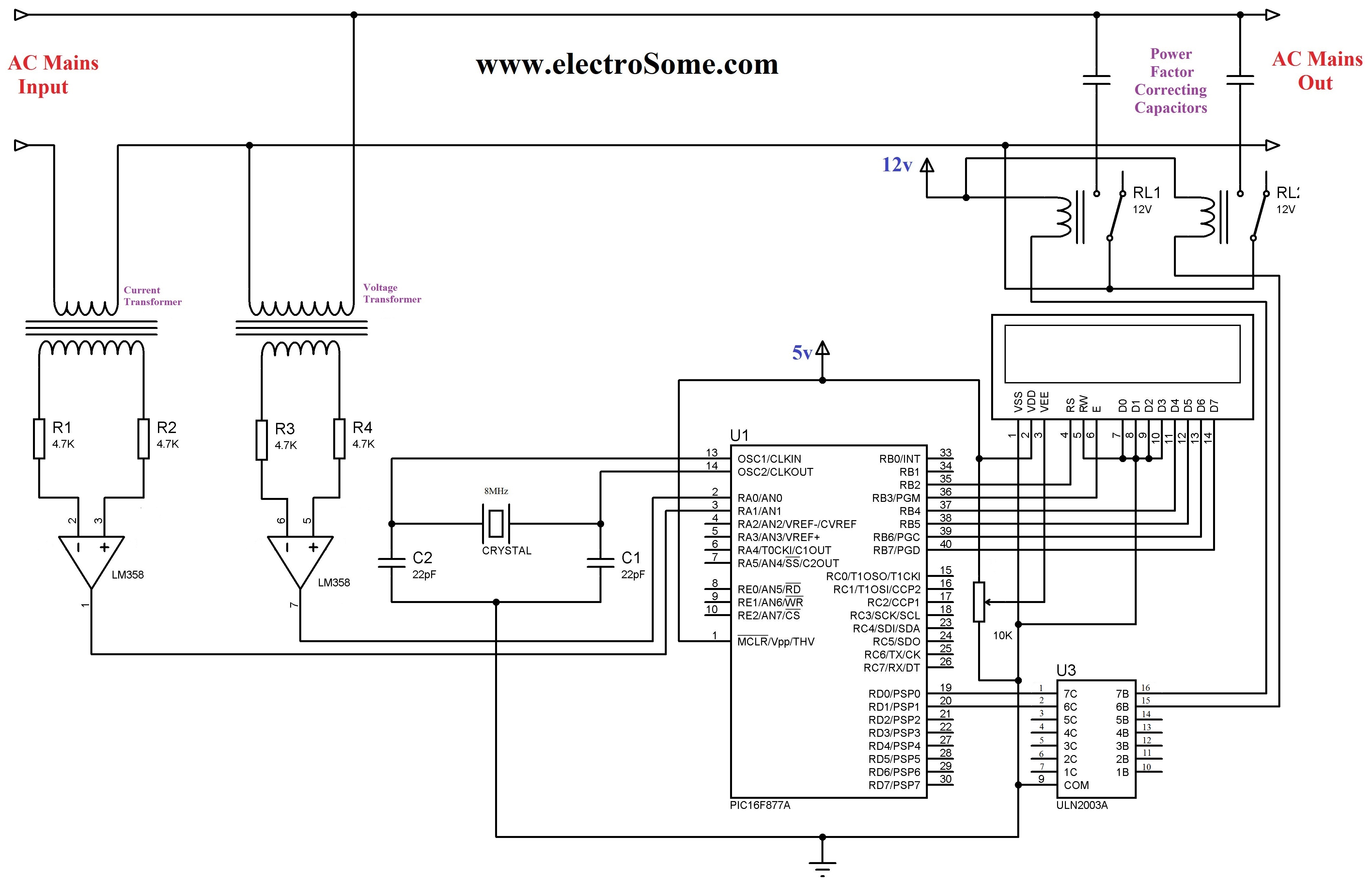
The 230 V, 50 Hz supply is stepped down using a voltage transformer, while a current transformer is utilized to extract the current waveforms. The output of the voltage transformer corresponds to the voltage across the load, and the...
This document describes an electronic winding machine with manual, electric, and semi-automatic features. The specific example highlighted includes an electronic counting function that assists users in managing motor windings. The circuit design consists of various components as illustrated in...

An electronic calculator features an automatic counting interface circuit, as illustrated in the accompanying figures. Figure (a) depicts a stroke switch controlled via optocoupler B. Figure (b) shows the application of a reed switch (KR) for pulse control signals....
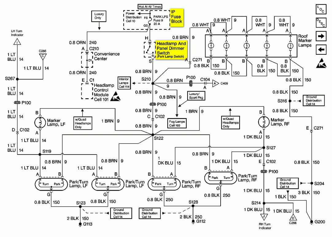
The turn signals, hazard lights, stop lights, and headlights are functioning properly. However, the tail lights do not operate when the headlights are on. The bulbs appear to be in good condition, as they were tested by switching the...
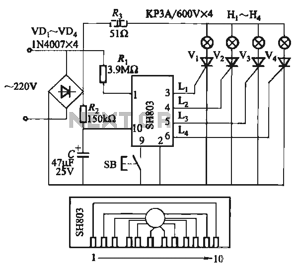
The circuit utilizes the SH803 flash IC, which can store eight different programs and offers various dimming options and light speed adjustments. A button is provided to trigger the control terminal SB on the 9-pin connector for program selection,...
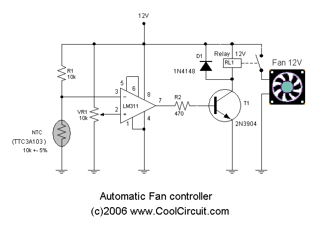
Automatic fan control circuit. This circuit turns a 12V DC fan or CPU fan on or off based on temperature readings. The temperature can be adjusted using VR1. The automatic fan control circuit operates by monitoring the temperature of...