
Push Off Push On
The bistable circuit configuration using the 555 timer is an effective solution for applications requiring a simple toggle action. The push-button switch serves as a user interface, allowing for intuitive control over the state of the circuit. The use of the internal Schmitt trigger simplifies the design by eliminating the need for external components typically associated with signal conditioning.
The circuit’s reliance on the stored charge within the capacitor provides a reliable mechanism for state retention, ensuring that the output remains stable during button presses. The inclusion of resistors Rb is critical for maintaining the input voltage within the specified dead-band range, preventing erratic behavior during operation.
The open-collector output at pin 7 is particularly advantageous, as it allows for the integration of external components, such as relays, without overloading the timer. This flexibility enables the design of various application circuits that can be activated or deactivated based on the state of the bistable circuit.
Furthermore, the power-up reset feature enhances the reliability of the circuit by ensuring that it starts in a known state, avoiding unintended behavior during initialization. The memory effect provided by the capacitor and resistor Rt is essential for preventing false triggering due to mechanical noise from the push-button switch.
Overall, this bistable 555 timer circuit exemplifies a robust and versatile solution for applications requiring a toggle switch mechanism, with the added benefits of simple construction and minimal component requirements.The ubiquitous 555 has yet another airing with this bistable using a simple push-button to provide a push-on, push-off action. It uses the same principle of the stored charge in a capacitor taking a Schmitt trigger through its dead-band.
Whereas the Schmitt trigger in that reference was made from discrete components, the in-built dead-band arising from the two comparators, resistor chain and bistable within the 555 is used instead. The circuit demonstrates a stand-by switch, the state of which is indicated by illumination of either an orange or red LED, exclusively driven by the bipolar output of pin 3. Open-collector output (pin 7) pulls-in a 100-mA relay to drive the application circuit; obviously if an ON status LED is provided elsewhere, then the relay, two LEDs and two resistors can be omitted, with pin 3 being used to drive the application circuit, either directly or via a transistor.
The original NE555 (non-CMOS) can source or sink 200 mA from / into pin 3. Component values are not critical; the dead-band` at input pins 2 and 6 is between 1/3 and 2/3 of the supply voltage. When the pushbutton is open-circuit, the input is clamped within this zone (at half the supply voltage) by two equal-value resistors, Rb.
To prevent the circuit powering-up into an unknown condition, a power-up reset may be applied with a resistor from supply to pin 4 and capacitor to ground. A capacitor and high-value resistor (Rt) provide a memory of the output state just prior to pushing the button and creates a dead time, during which button contact bounce will not cause any further change.
When the button is pressed, the stored charge is sufficient to flip the output to the opposite state before the charge is dissipated and clamped back into the neutral zone by resistors Rb. A minimum of 0. 1 µF will work, but it is safer to allow for button contact-bounce or hand tremble; 10 µF with 220 k gives approximately a 2-second response.
🔗 External reference
Related Circuits
Battery-operated devices are increasingly prevalent, and manufacturers strive to minimize current consumption to enable prolonged operation on battery power. However, even minimal current draw can lead to battery depletion if the device is not powered off, resulting in a...
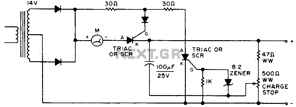
Adjust by setting the 500-ohm resistor while attached to a fully charged battery. The circuit involves a 500-ohm resistor that is to be adjusted while it remains connected to a fully charged battery. This setup is typically used in applications...
Offline telephone tester. This circuit allows for testing a telephone instrument without the need for a telephone line. The design is straightforward. The offline telephone tester circuit is designed to evaluate the functionality of telephone instruments independently of an active...
A request has been made to design a unique outdoor Christmas decoration in the form of an LED-illuminated star. The objective is to create a very bright display using 30 ultra-bright 8mm LEDs. The plan includes sanding the domes...
Most devices used in amplifier output stages exhibit significant non-linearity, with transistors (both bipolar and FET) being particularly problematic. These components are almost always employed within a global feedback loop to mitigate their non-linear characteristics. Similarly, tetrode and pentode...
Using a switch to power up your microcontroller projects may not be a good idea if you need to "wake" the PIC during some events. For example: A metal detector sends a pulse indicating a car is ready to...
Warning: include(partials/cookie-banner.php): Failed to open stream: Permission denied in /var/www/html/nextgr/view-circuit.php on line 713
Warning: include(): Failed opening 'partials/cookie-banner.php' for inclusion (include_path='.:/usr/share/php') in /var/www/html/nextgr/view-circuit.php on line 713