LF or HF field strength meter
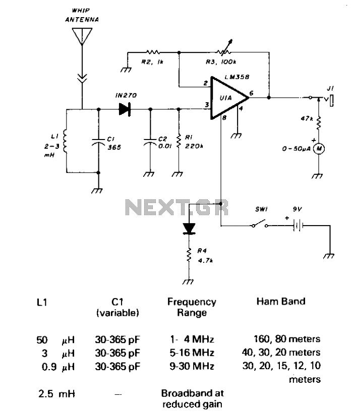
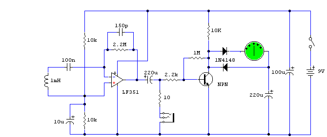
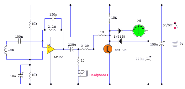
CI and LI resonate on the 1750-meter band, with coverage from 150 kHz to 500 kHz. LI can be slug-tuned for 160 to 190 kHz coverage alone, or a 2.5 mH choke can be used for LI, if desired, utilizing CI for tuning. A 1N270 germanium diode rectifies the RF signal, and C2 is charged at the peak RF level. This DC level is amplified by an LM358. The gain is determined by R2 and R3, a 100-kilohm linear potentiometer that varies the DC gain from 1 to 100, driving the 50 microampere meter. This field strength meter need not be limited to LF use. The table shows the LI and CI values for HF operation and broadband operation.
The circuit employs a resonant tank configuration formed by components CI and LI, specifically designed to operate effectively within the 1750-meter band. The frequency range of operation extends from 150 kHz to 500 kHz, making it suitable for various applications in low-frequency (LF) and high-frequency (HF) domains.
LI can be adjusted using slug tuning to allow for precise coverage between 160 kHz and 190 kHz. For broader tuning capabilities, a 2.5 mH choke can be incorporated in place of LI, permitting CI to maintain its role in tuning. This flexibility in component selection enhances the circuit's adaptability to different operational requirements.
The RF signal is rectified by a 1N270 germanium diode, which is known for its low forward voltage drop, thus ensuring efficient signal processing. The rectified signal is then utilized to charge capacitor C2, which captures the peak RF voltage level. This capacitor plays a crucial role in smoothing the rectified output, providing a stable DC voltage for further amplification.
The LM358 operational amplifier is employed to amplify the DC level obtained from C2. The gain of the amplifier is adjustable and is determined by the resistor values of R2 and R3, which form a voltage divider configuration with a 100-kilohm linear potentiometer. This design allows the user to vary the gain from 1 to 100, enabling fine-tuning of the output signal that drives a 50 microampere meter. The meter provides a visual indication of the field strength, making it a valuable tool for RF signal measurement.
Additionally, the circuit is not limited to LF applications, making it versatile for HF operations as well. The accompanying table outlines specific values for LI and CI, facilitating both HF operation and broadband applications. This detailed configuration ensures comprehensive functionality across a wide range of frequencies, catering to various electronic measurement needs.CI and LI resonate on the 1750 meter band, with coverage from 150 kHz to 500 kHz. LI can be slug-tuned for 160-to-190 kHz coverage alone or a 2.5 mH choke can be used for LI, if desired, using CI for tuning. A 1N270 germanium diode rectifies the RF signal and C2 is charged at the peak RF level. This dc level is amplified by an LM358. The gain is determined by R2 and R3, 1 100-kilohm linear potentiometer that varies the dc gain from 1 to 100, driving the 50 microampere meter.
This field strength meter need not be limited to LF use. The Table shows the LI and CI values for HF operation and broadband operation.
