
Electromagnetic Field Probe with Meter
The circuit consists of several key components that work together to detect electromagnetic fields. The primary sensing element is a probe that integrates a radial inductor and a screened cable to minimize interference. The op-amp serves as the initial amplification stage, where the weak signals from the probe are amplified before being further processed. The choice of a BC109C transistor ensures adequate amplification of the AC signal, making it suitable for detection purposes.
The full-wave rectification stage is crucial for converting the AC signal into a DC voltage that can be read by the panel meter. This involves the use of diodes that allow current to flow in one direction, effectively converting the alternating signal into a direct current signal. The capacitor in this stage smooths out the rectified voltage, providing a stable reading on the meter.
The use of stereo headphones allows for real-time monitoring of audio frequencies, enabling the user to hear the signals picked up by the probe. The design also accommodates various signal sources, whether from an audio signal generator or ambient electromagnetic fields generated by electrical devices.
In practical applications, it is essential to consider the layout and placement of the circuit components. The proximity of the audio circuit to transformers or other inductive components can introduce noise and hum, which may affect performance. The shift towards toroidal transformers in modern designs helps mitigate such issues due to their reduced electromagnetic fields. Overall, this tester is a versatile tool for detecting stray EM fields in various environments, making it valuable for troubleshooting and experimentation in electronics.This tester is designed to locate stray electromagnetic (EM) fields. It will easily detect both audio and RF signals up to frequencies of around 100kHz. Note, however that this circuit is NOT a metal detector, but will detect metal wiring if it conducting ac current. Frequency response is from 50Hz to about 100kHz gain being rolled off by the 150p capacitor, the gain of the op-amp and input capacitance of the probe cable. Stereo headphones may be used to monitor audio frequencies at the socket, SK1. I used a radial type inductor with 50cm of screened cable threaded through a pen tube. The cable may be used with a plug and socket if desired. My probe is shown below: The output signal from the op-amp is an ac voltage at the frequency of the electro-magnetic field. This voltage is further amplified by the BC109C transistor, before being full wave rectified and fed to the meter circuit.
The meter is a small dc panel meter with a FSD of 250uA. Rectification takes place via the diodes, meter and capacitor. If you have access to an audio signal generator you can apply an audio signal to the windings of a small transformer. This will set up an electromagnetic field which will be easily detected by the probe. Without a signal generator, just place the probe near a power supply, mains wiring or other electrical device.
There will be a deflection on the meter and sound in the headphones if the frequency is below 15KHz. Switch on, plug in headphones (optional) and move the probe around. Any electrical equipment should produce a hum and indicate on the meter. I remember once building a high gain preamp (for audio use). I made a power supply in the same enclosure. The preamp worked, but suffered from an awful mains hum. This was not directly from ripple on the power supply as it was regulated and well smoothed. What I had done was built the audio circuit on a small piece of veroboard, and placed it within a distance that was less than the diameter of the transformer. The transformers own electromagnetic field was responsible for the induced noise and hum. I should however note, that this was when I was new to electronics with very little practical experience.
You can now buy toroidal transformers which have a much reduced hum field. 🔗 External reference
Related Circuits
An analog VU meter is commonly found in audio equipment to indicate signal levels in volume units. It features a peak LED and compares the response of the VU meter (represented by a black line) with the instantaneous input...
Free domains and hosting with up to 1GB of disk space, unlimited transfer, and access to PHP as well as 5 MySQL databases. The maximum size of a single file is not limited. This service offers a robust web hosting...
We are OUT OF STOCK on the surplus brushless DC motor we used to build this project, and since it's surplus we cannot get any more. The resistor and capacitor values listed in the schematic and on the PC...
This circuit utilizes the SIEMENS and UAA180 rectification measurement circuits for accurate signal processing, centered around the TL072 integrated circuit (IC2B). Calibration occurs in 3dB increments, ensuring a high level of precision for measuring incoming acoustic signals. The LEDs...
A basic digital voltmeter circuit utilizing the Harris Semiconductor ICL7107 is presented. It operates within a 2-V range. Calibration involves applying a known voltage of 1.2 V to the input and adjusting resistor R3 to achieve an accurate reading...
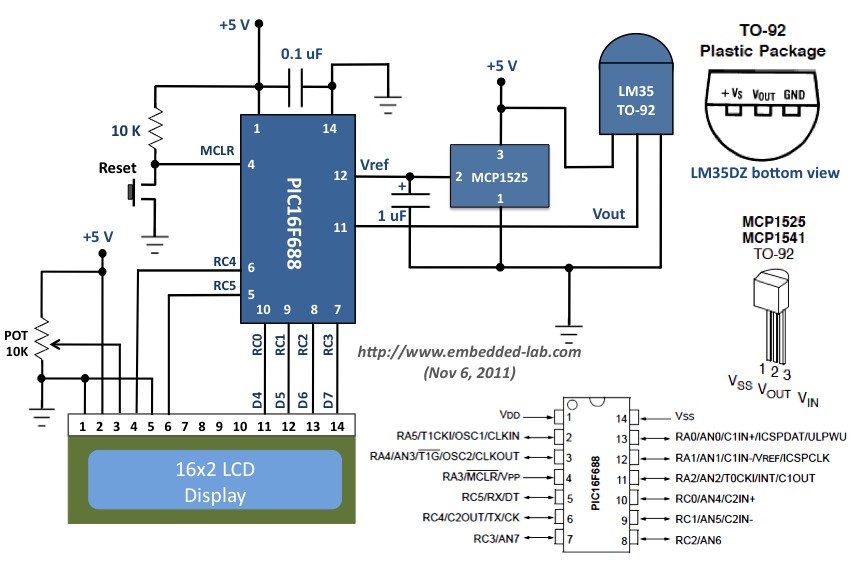
This document outlines a revised version of an LM35-based digital thermometer project previously shared. While it is a straightforward project, it remains popular among beginners learning about microcontrollers. The initial version contained a flaw, as some readers noted that...
Warning: include(partials/cookie-banner.php): Failed to open stream: Permission denied in /var/www/html/nextgr/view-circuit.php on line 713
Warning: include(): Failed opening 'partials/cookie-banner.php' for inclusion (include_path='.:/usr/share/php') in /var/www/html/nextgr/view-circuit.php on line 713