
LB1416 36 five sections and Ten-segment level display a
The LB1416/26/36 circuit is designed to provide a versatile solution for visual display applications, particularly in audio level monitoring and other electronic instrumentation. The dual input configuration allows for simultaneous monitoring of two different signals, making it highly effective in scenarios where comparative analysis is required. The use of voltage comparators enhances the circuit's ability to accurately reflect the voltage levels of the inputs, ensuring that the corresponding LEDs illuminate in response to the input signals.
The internal architecture of the LB1416/26/36 includes precision amplifiers that amplify the input signals before they are processed by the comparators. This amplification stage is critical for ensuring that even low-level signals can be effectively displayed. The incorporation of crossing rectifiers aids in converting AC signals to DC, making the circuit adaptable to various input types.
Adjustability is a key feature of this circuit, allowing users to fine-tune the brightness of the LEDs according to their specific requirements. The external resistor used for current control plays a vital role in defining the intensity of the LED output, which can be crucial in applications where visibility is important.
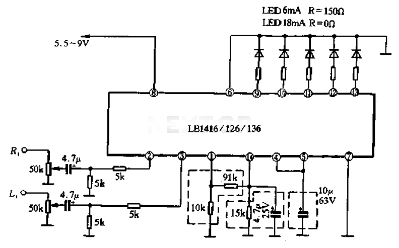
In summary, the LB1416/26/36 circuit represents a well-engineered solution for driving multiple LEDs in response to varying input signals, with features that support dual-channel operation and adjustable output levels. Its design principles ensure reliable performance across a broad range of applications, from audio systems to general-purpose voltage monitoring.Another common single five lamp drive circuit is: LB1416/26/36, the circuit is a double row of finned-line 14 pin package. Its interior has two input amplifier and five voltage comparator can drive AC, DC meter, but also to drive the light emitting diodes. As the circuit has two inputs, so it can make single-output level display, and can be used for dual output power supply voltage level display o accommodate a wide range of the circuit, to 5. 5 ~ 16V enter the release of internal amplifier with two and a half crossing rectifiers, can provide a constant excitation current of LED, can be controlled by an external resistor the size of its current system to adjust LED brightness.
Parameters LB1416/26/36 in Table 4-80 circuit supply voltage range of 5.5 ~ 16V, the supply current is 12mA. Figure 4-49 is a five paragraphs and paragraph level with ten LB1416/26/36 composed of display circuit.
LB1416/26/36 has two inputs, only one set of output terminals, when it is used as a dual display drivers, in order to guarantee the consistency of the two input signals permit displayed, when the need to adjust each channel separately adjust o If you adjust right channel should be in the right sound channel input terminal OdB signal, adjust 51kS1 potentiometer input for LB1416 should make Lm luminous; then enter 0dB signal in the left channel, using the same method to make LD3 light. LB1426 and 1436 are available for the same square method to adjust o
Related Circuits
A tiny sandwich flag connected perpendicular to the motor spindle aids observation of how long it takes to complete one full rotation. This worked initially, as each burst from the capacitor barely moved the flag 1/4 of a rotation....
This schematic represents a simple water or liquid level sensor relay switch circuit, designed to control electronic appliances based on water levels. The circuit is particularly useful for automatically turning off a water pump when a water tank, pool,...
It is entirely feasible and acceptable to control various outputs while sitting at a PC terminal. A simple hardware circuit and software are utilized to interface with a 7-segment rolling display. The printer port of a PC provides a...
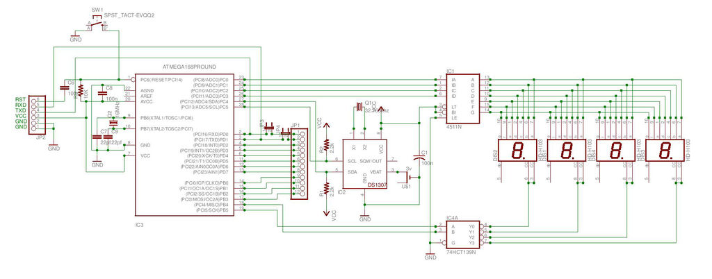
This is the second instructable focused on creating a digital watch as a learning experience. An Atmega644 chip from a Sanguino was available, which would have sufficed, but the intention was to burn an Arduino bootloader and test its...
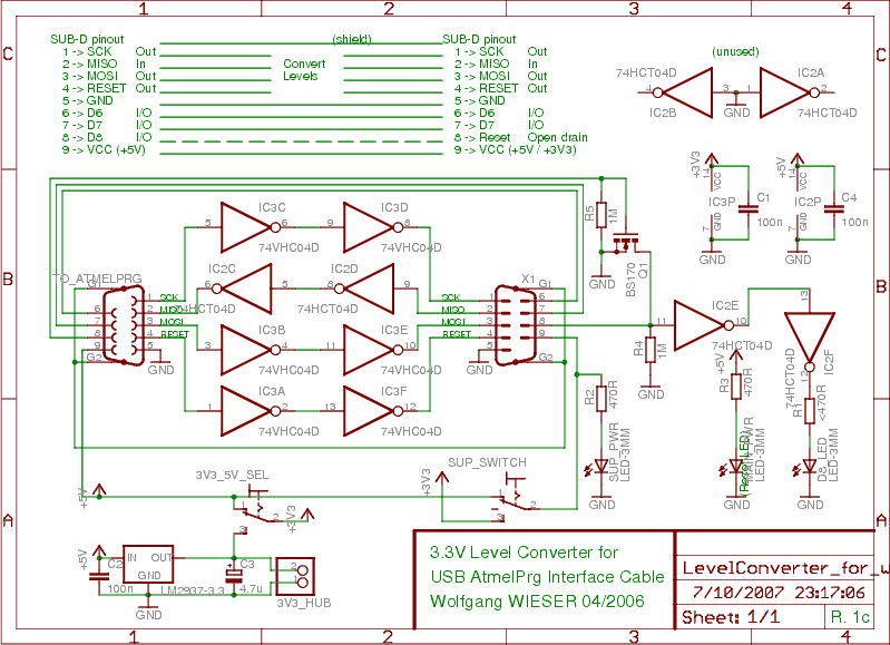
To program devices operating at 3.3V, such as SPI-based AVRs or JTAG-based CPLDs, level conversion is necessary for input and output signal levels. A 5V input may not register as HIGH at 3.3V, and a 3.3V device can be...
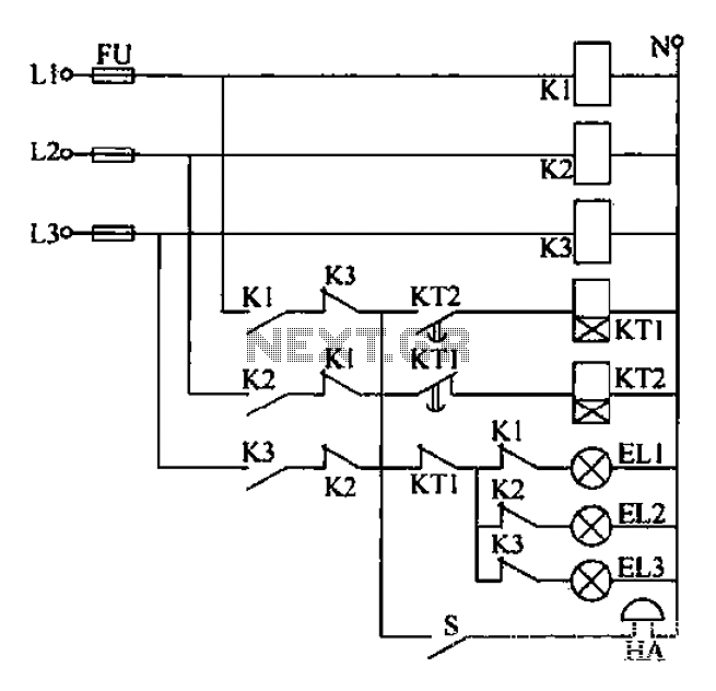
Any power supply and distribution sector should include phase sequence detection to ensure that the power supply phase sequence remains stable and unchanged. Additionally, any irreversible electromechanical product should also incorporate phase sequence detection to verify the phase sequence...
Warning: include(partials/cookie-banner.php): Failed to open stream: Permission denied in /var/www/html/nextgr/view-circuit.php on line 713
Warning: include(): Failed opening 'partials/cookie-banner.php' for inclusion (include_path='.:/usr/share/php') in /var/www/html/nextgr/view-circuit.php on line 713