
direct driving LCD

The choice of display in electronic designs is critical, particularly when interfacing with microcontrollers. The mentioned LCD, with its greater number of pins compared to the microcontroller, poses potential challenges in terms of pin allocation and complexity in programming. The inability to expand the image for a clearer view further complicates the assessment of its compatibility and usability.
In contrast, a Hitachi-compliant alphanumeric display with an onboard driver is suggested as a more efficient alternative. Such displays typically integrate the necessary control circuitry within the module itself, significantly reducing the number of I/O pins required from the microcontroller. This integration not only simplifies the hardware connections but also minimizes the complexity of the software code needed to drive the display.
Using a Hitachi-compliant display allows developers to leverage established libraries and example codes, which can expedite the development process. These displays usually adhere to standard protocols, ensuring compatibility with a wide range of microcontrollers. As a result, the overall design becomes more streamlined, making it easier to manage resources and optimize performance.
In summary, when selecting a display for microcontroller applications, it is crucial to consider the number of pins, the complexity of the interfacing code, and the potential for future scalability. The recommendation to opt for a Hitachi-compliant alphanumeric display is based on these factors, aiming to enhance both the functionality and efficiency of the electronic design.The LCD in question appears to have more pins than the microcontroller, I could not expand the image to get a better look. Unless you are adamant about using this display, I recommend obtaining a hitachi compliant alphanumeric display (onboard driver), this will require fewer I/O pins and less uC code.
🔗 External reference
Related Circuits
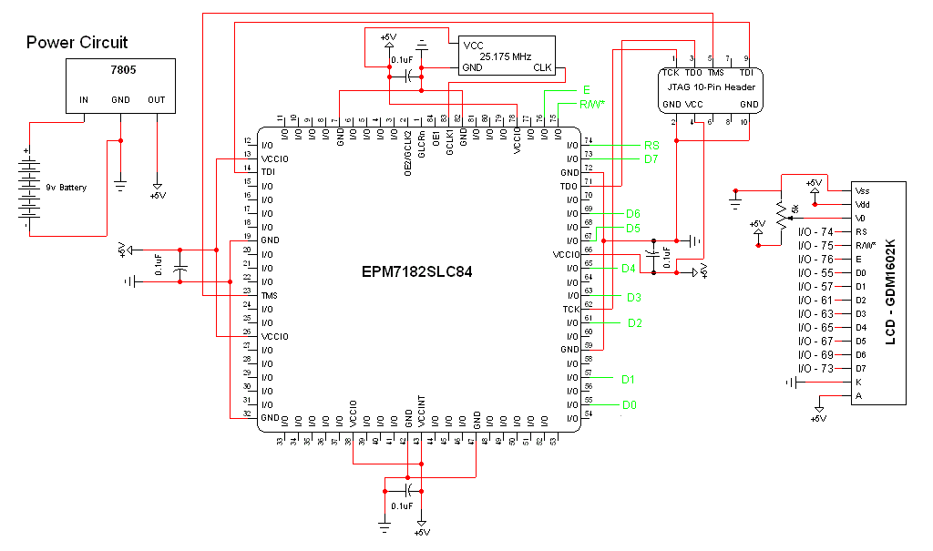
The schematic for this project is a modified version of the CPLD development board schematic. Several new components have been added for this project, and the completed schematic is presented below. The primary components in the schematic include the...
The rectifier bridge voltage is determined by the U2 element; refer to its datasheet for the maximum voltage specifications. The minimum voltage at this pin should not fall below approximately 9V, or 6.5V if low-dropout type U2 and U3...
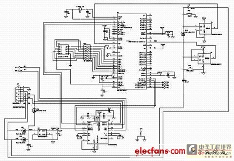
This text discusses the MSC1210 microcontroller as the core of a high-accuracy temperature measurement system, which includes signal processing and communication capabilities. The system is designed for easy expansion, allowing for accurate measurements and fast data acquisition. The hardware...
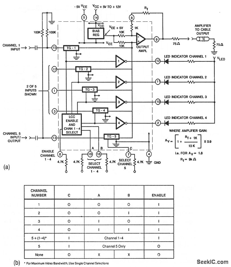
This circuit illustrates a CA3256 switch/amplifier configured for a direct-coupled output. One of four channels can be selected in parallel with channel 5. The analog switches of channels 1 to 4 are digitally controlled by logic. A VEE of...

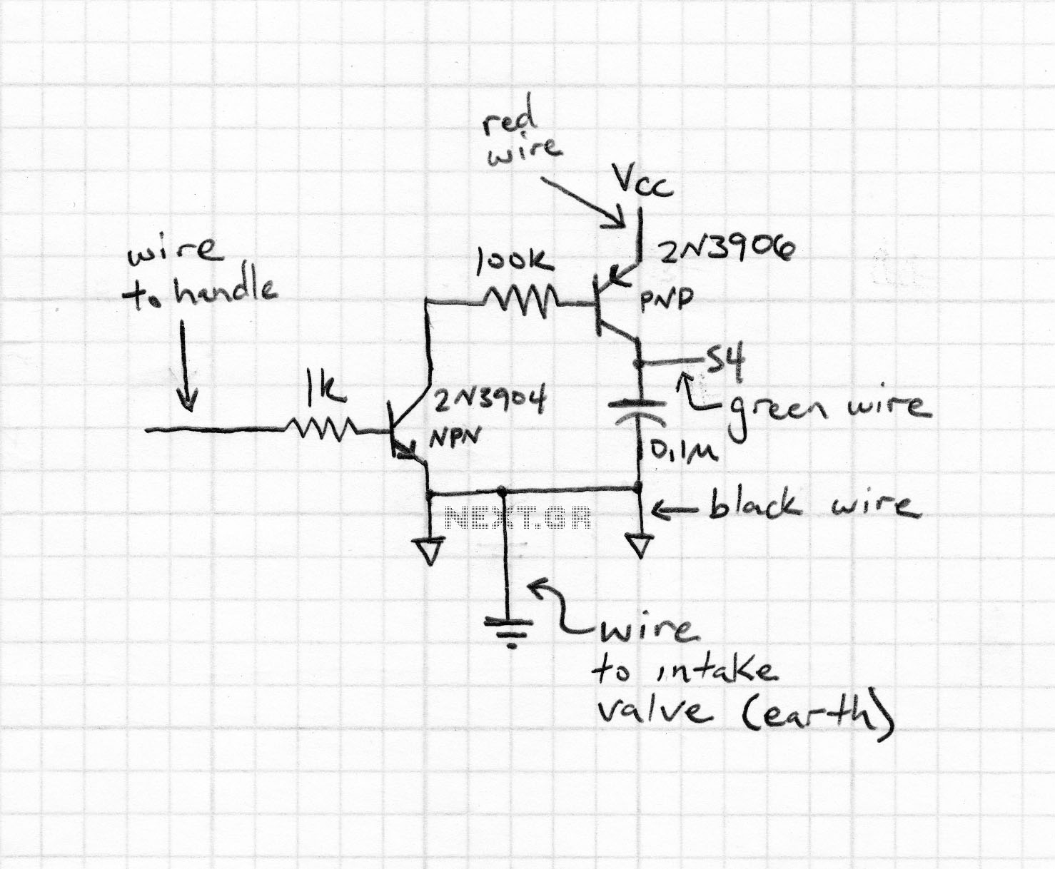
An NPN bipolar transistor is typically utilized for relay switching, particularly with 12V coil-rated relays, as it helps maintain circuit separation. A diode is also added to prevent issues. The necessity of driving the relay with a transistor depends...
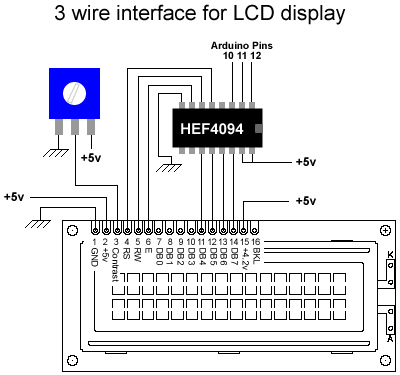
This post discusses the work previously conducted by Tomek regarding the wiring of LCD displays using a 4-bit configuration. The primary concept involves consolidating the seven pins required to operate the LCD into just three using a shift register,...