
lf365 A digital thermometer or talk I2C to your atmel microcontroller

The I2C protocol's functionality is enhanced by its simplicity and efficiency, allowing multiple devices to communicate over just two wires. The SDA line carries the data, while the SCL line provides the clock signal, enabling synchronized communication between the master and slave devices. Each device on the bus must have a unique address, allowing the master to select which slave to communicate with. The acknowledgment mechanism ensures data integrity, as the slave confirms receipt of the data sent by the master. This protocol is particularly advantageous in applications where space and component count must be minimized, as it eliminates the need for additional components typically required for RS232 communication. The design considerations for implementing I2C with the Atmega8 include ensuring proper pull-up resistor values, managing device addressing, and establishing a reliable power supply for each connected device. Overall, the I2C protocol is a robust solution for interfacing the Atmega8 microcontroller with various sensors and peripherals in measurement systems.The Atmega8 microcontroller from Atmel has plenty of digital and analog input/output lines. It is the ideal device to develop any kind of measurement equipment. A pre-requisite for this article is that you have the GCC AVR programming environment installed as described in my "Programming the AVR microcontroller with GCC, libc 1. 0. 4" article. If y ou want to avoid troubles with the installation you can of course use the AVR programming CD from When you use such an advanced device as a microcontroller to measure analog or digital signals then you want of course interfaces to evaluate the data or send commands to the microcontroller. In all the articles presented here in the past we always used rs232 communication with the UART that is included in the microcontroller.
The problem is that this requires an additional MAX232 chip and 4 extra capacitors. Atmel suggests also that an external crystal osciallator is required for the UART communication to work reliably. In any case it is a lot of extra parts. and we can avoid them! The amount of data to transfer between PC and microcontroller is usually very small (just a few bytes).
Speed it therefore no issue at all. This makes the I2C bus/protocol suitable for this task. I2C (prounouce "eye-square-see") is a two-wire bidirectional communication interface. It was invented by Philips and they have protected this name. This is why other manufacturers use a different name for the same protocol. Atmel calls I2C "two wire interface" (TWI). Many of you might already be using I2C on their PCs without knowing it. All modern motherboards have an I2C bus to read temperatures, fan speed, information about available memory. all kind of hardware information. This I2C bus is unfortunately not available on the outside of the PC (there is no physical connector).
Therefore we will have to invent something new. The datasheet of the Atmega8 (see references) has actually a very detailed description starting on page 160. I will therefore present here just an overview. After this overview you will be able to understand the description in the datasheet. On the I2C bus you always have one master and one or several slave devices. The master is the device that initiates the communication and controls the clock. The two wires of this bus are called SDA (data line) and SCL (clock line). Each of the devices on the bus must be powered independently (same as with traditional rs232 communication).
The two lines of the bus are normally connected via 4. 7K pullup resistors to logically "High" (+5V for 5V ICs). This gives an electrical "or" connection between all the devices. A device just puls a line to GND when it wants to transmit a 0 or leaves it "High" when it sends a 1. The master starts a communication by sending a pattern called "start condition" and then addresses the device it wants to talk to.
Each device on the bus has a 7 bit unique address. After that the master sends a bit which indicates if it wants to read or write data. The slave will now acknowledge that it has understood the master by sending an ack-bit. In other words we have now seen 9 bits of data on the bus (7 address bits + read_bit + ack-bit): Next we can receive or transmit data. Data is always a multiple of 8 bits (1 byte) and must be acknowledged by an ack-bit. In other words we will always see 9-bit packets on the bus. When the communication is over then the master must transmit a "stop condition". In other words the master must know how much data will come when it reads data from a slave. This is however not a problem since you can transmit this information inside the user protocol. We will e. g use the zero byte at the end of a string to indicate that there is no more data. SDA H - /- /- /- L -/ -/ -/ -. SCL H - /- /- /- /- /- L -/ -/ -/ -/ -/ -. | START | 1 | 1 | 0 | 1 | 0 | One of the best things about this protocol is that you do not need a precise and
🔗 External reference
Related Circuits
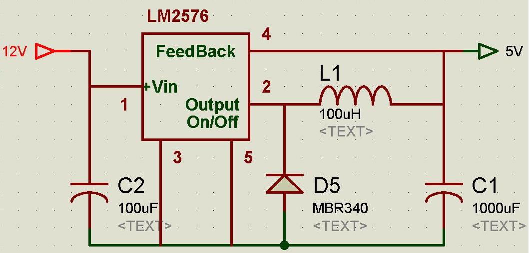
A regulated and noise-free power supply voltage is essential for microcontrollers and other components such as amplifiers, filters, and GPS devices. Voltage surges in the supply voltage can permanently damage embedded systems. A voltage regulator must maintain the output...
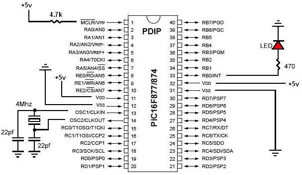
PIC development/testing board. This is a PCB design for a basic PIC16F877 development board. All that is required is a 4 MHz crystal, two 22 pF capacitors, and one 4.7 kΩ resistor. The PIC16F877 development board is designed to facilitate...
This circuit is designed for precise measurement of temperature in degrees Celsius. It features a transmitter section that converts the output voltage from the temperature sensor, which is proportional to the measured temperature, into a frequency signal. This frequency...
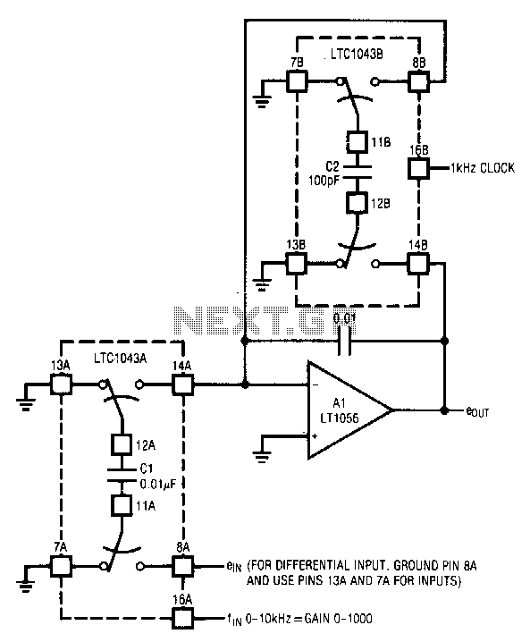
The circuit utilizes the LTC1043 in a variable gain amplifier configuration, which offers continuously adjustable gain, gain stability of 20 ppm/°C, and supports both single-ended and differential inputs. Two separate LTC1043 devices are employed in the design. The LTC1043B...
The TRW-24G connector pins are quite small, approximately 1mm apart. To address this issue, an adaptor PCB has been ordered to convert the small connector of the RF module to a standard pin connector. The pin arrangement of the...
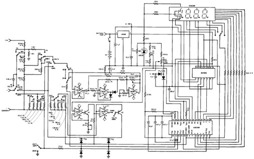
The following circuit illustrates the design of a simple digital multimeter circuit diagram. This circuit employs the ADD3501. Features include the combination of voltage measurements, among others. The circuit design for a simple digital multimeter utilizing the ADD3501 integrates several...