
transistors IR Emitter/Detector with 555 timer alarm
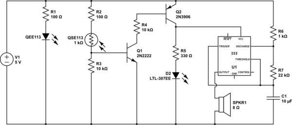
The circuit is designed to monitor the status of a tube, activating a piezo buzzer as an alert when the tube is empty. The transition from a 5V to a 12V power supply requires careful consideration of component ratings and values to ensure proper functionality.
The piezo buzzer can be connected in series with the transistor QEE113, which acts as a switch. When the tube is detected as empty, the transistor is activated, allowing current to flow through the buzzer, producing sound at regular intervals. The choice of R1 is critical in limiting the base current to the transistor. While a 220-ohm resistor rated for 1W is the standard recommendation for 12V operation, substituting a 510-ohm, 1/4W resistor is feasible due to the short distance of 1 inch, which minimizes voltage drop and maintains adequate current flow.
To calculate the appropriate resistor values for the transistors when changing from 5V to 12V, Ohm's Law (V = IR) can be utilized. The base current can be adjusted based on the desired collector current and the transistor's current gain (hFE). For instance, if the desired collector current is 50mA, and the hFE of QEE113 is known, the base current can be calculated as follows:
1. Determine the required base current (Ib) using the formula:
Ib = Ic / hFE
2. Use Ohm's Law to find the necessary resistor value (R):
R = (V_supply - V_be) / Ib
Where V_be is typically around 0.7V for silicon transistors. This calculation will yield the resistor value required to ensure the transistor operates effectively at the new supply voltage. By applying these principles, the circuit can be optimized for the 12V power supply while maintaining its intended functionality.This circuit detects when a tube is empty and pulses a piezo buzzer in. 5 second intervals. I have it working with 5v on a breadboard, but I need to move it to 12v from a wall wart. Secondly, with 12v R1 should be 220 1W, but I want to stick with 1/4W resistors, maybe 510. Is that possible I realize that will bring down the 50ma current to QEE113 to 22mA, but my distance is only 1" so I think it will be enough power. Thridly, I`m not sure how to calculate the size of resistors needed to go to the transistors. The values I have are from various samples I found on the net for 5v. Is there a formula that tells me what they need to be for 12v. I`m not able figure that out from the datasheets. 🔗 External reference
Related Circuits
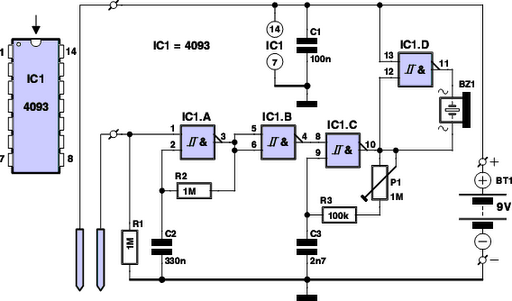
Have you ever observed the stairs to an upper story in your house transform into a waterfall? Or perhaps you returned home to find your aquarium fish attempting to swim across the carpet? For your sake, it is hoped...

This is an infrared-based broken beam alarm designed to protect doors and entry passages. It emits a loud alarm when someone crosses the invisible infrared barrier. The infrared-based broken beam alarm system operates by utilizing a pair of infrared emitters...
This circuit was developed in response to requests from website visitors for a timer that can emit a beep after intervals of one, two, three minutes, and so forth, for jogging purposes. As depicted in the circuit diagram, SW1...
This LED flasher circuit utilizes a 555 integrated circuit (IC) and is designed to drive multiple LEDs. Notably, connecting several LEDs in series does not increase the power consumption. The LED flasher circuit based on the 555 timer IC is...

The utility vehicle anti-theft alarm circuit consists primarily of two main components essential for its operation. The security circuit is activated when the vehicle owner departs from the vehicle, utilizing an anti-theft switch (S B) to engage the alarm...
This is the first electronic circuit designed from scratch, marking the initial experience with programming a microcontroller (MCU), the first application written in assembly language, and the second homemade printed circuit board (PCB). While it is common for individuals...