
Lie Detector
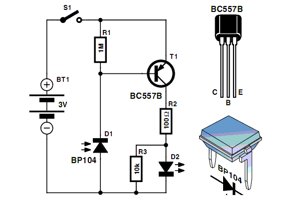
This circuit is based on the fact that a person's skin resistance changes when they sweat (sweating because they're lying). Dry skin has a resistance of about 1 million ohms, whereas the resistance of moist skin is reduced by a factor of ten or more. More: Resistors R1 and R2 form a voltage divider. They have resistances of 1 000 000 ohms (1 mega ohm) and, because their values are equal, the voltage at the upper probe wire is half the battery voltage (about 4.5 volts).
A person holding the probe wires will experience variations in skin resistance based on their physiological responses, which can be detected by the circuit.
The Lie Detector circuit operates on the principle of measuring the electrical resistance of the skin, which varies with moisture levels due to sweat production. The circuit includes three transistors (TR1, TR2, and TR3) that are configured to amplify the changes in voltage caused by fluctuations in resistance. The transistors serve to switch the LEDs (L1 and L2) on and off, indicating the level of resistance detected.
Resistors R1 and R2 are crucial as they form a voltage divider network. Their equal resistance values ensure that the voltage at the midpoint of the divider is half the supply voltage, which allows for sensitive detection of changes in resistance. When a person is calm, the skin resistance remains high, and the output voltage remains stable. However, as the subject begins to sweat due to stress or deception, the skin's resistance decreases, altering the voltage levels across the divider.
The variable resistor (VR1) allows for calibration of the circuit, accommodating different skin types and environmental conditions, ensuring more accurate readings. The capacitor (C1) is used to filter out noise in the signal, providing a smoother output for the detection circuit.
Overall, the Lie Detector circuit is a practical application of basic electronic components to create a device that can infer psychological states based on physiological responses. The combination of transistors, resistors, and LEDs provides a simple yet effective means of visual feedback for the user.The circuit diagram of the Lie Detector is shown above. It consists of three transistors (TR1 to TR3), a capacitor (C1), two lights or LEDs (L1 & L2), five resistors (R1 to R5), and a variable resistor (VR1). This circuit is based on the fact that a person`s skin resistance changes when they sweat (sweating because they`re lying).
Dry skin has a resistance of about 1 million ohms, whereas the resistance of moist skin is reduced by a factor of ten or more. Resistors R1 and R2 form a voltage divider. They have resistances of 1 000 000 ohms (1 mega ohms) and, because their values are equal, the voltage at the upper probe wire is half the battery voltage (about 4.5 volts). A person holding the probe wires w 🔗 External reference
Related Circuits

The SC9256 is a phase-locked loop (PLL) integrated circuit designed for digital tuning systems (DTS), featuring built-in 2 modulus prescalers. All functions are controlled through three serial bus lines. These integrated circuits are utilized to configure high-performance digital tuning...
A 2001 Chevrolet Cavalier has experienced a failure in one of the low beam headlights. Despite replacing the bulb, the headlight remains non-functional. Additionally, when the vehicle is shifted into gear, the daytime running lights flash multiple times before...
Men, in particular, appreciate the convenience of television remote controls, which can often lead to frustration for their female partners. Men seem to have a desire to understand what... The initial statement highlights a common dynamic in household technology usage,...

This circuit can be constructed using readily available low-cost components, some of which may be found in a junkbox. The specified value of 22 ohms for resistor R1 results in an average current of approximately 65 mA through the...
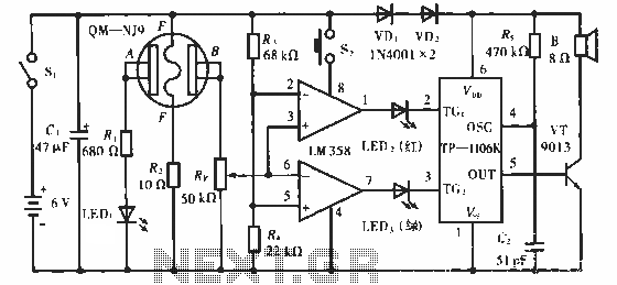
The QM-NJ9 is an alcohol sensor that detects the presence of alcohol by measuring the resistance values between points A and B. When alcohol is detected, the resistance decreases, leading to an increase in potential at point B. As...
The following circuit illustrates an AM Broadcast Detector Circuit Diagram. Features include a 10 kHz notch filter, which is suitable for low voltage single supply applications. The AM Broadcast Detector Circuit is designed to demodulate amplitude modulated (AM) signals, allowing...
Warning: include(partials/cookie-banner.php): Failed to open stream: Permission denied in /var/www/html/nextgr/view-circuit.php on line 713
Warning: include(): Failed opening 'partials/cookie-banner.php' for inclusion (include_path='.:/usr/share/php') in /var/www/html/nextgr/view-circuit.php on line 713