
AM Broadcast Detector

The AM Broadcast Detector Circuit is designed to demodulate amplitude modulated (AM) signals, allowing for the extraction of audio information from the RF carrier wave. The circuit typically consists of a diode, which serves as the demodulating element, and additional components such as resistors and capacitors that form the notch filter.
The inclusion of a 10 kHz notch filter is crucial in this design as it effectively attenuates unwanted frequencies around 10 kHz, which may arise from interference or noise in the transmission environment. This helps to enhance the clarity of the received audio signal. The circuit may utilize a low voltage single supply, making it suitable for battery-operated devices or applications where power efficiency is a priority.
In detail, the diode's forward bias allows it to conduct during the positive half-cycles of the AM signal, while blocking the negative half-cycles. This results in a pulsating DC output that corresponds to the audio envelope of the modulated signal. The output is then smoothed using a capacitor, which helps to filter out high-frequency components and provides a more stable audio signal.
The notch filter can be implemented using an R-C (resistor-capacitor) network, strategically designed to create a frequency response that minimizes gain at 10 kHz while allowing other frequencies to pass through. This is particularly beneficial in environments with multiple overlapping AM signals, as it helps to isolate the desired station.
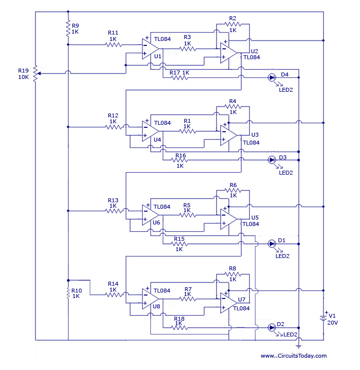
Overall, this AM Broadcast Detector Circuit is an essential tool for receiving AM signals, particularly in low-power applications, and its design can be adapted for various frequencies and environmental conditions to optimize performance.The following circuit shows about AM Broadcast Detector Circuit Diagram. Features: with 10KHz notch filter, fits well with a low voltage single .. 🔗 External reference
Related Circuits
The design originated from the interest in discovering a new technique for analog to digital conversion. The two types of ADC (Analog to Digital Converter) that influenced the development of this circuit are the Flash Type ADC and the...
The motion detector circuit consists of two components: the emitter and the sensor/detector. The emitter is constructed using an infrared emitting diode that is reverse-biased to a 5-volt source. The sensor employs the MRD821 to detect the infrared beam...

One of the simplest methods of metal detecting is through a beat frequency oscillator. The circuit consists of two balanced oscillators: one provides a reference signal, while the other acts as the detector element. The frequency of the reference...
Is there a way to automatically turn on an LED when it gets dark? A version was created using a relay and photoresistor that functioned properly, but concerns arose regarding potential battery drain. The project aims to integrate with...
This battery-powered metal detector utilizes four exclusive-OR gates from the 4030 CMOS integrated circuit. The gates are configured as twin oscillators, with a search coil acting as the inductance element in one of the oscillators. When the coil approaches...
When the unit is positioned near a live conductor, whether insulated or buried in plaster, capacitive coupling occurs between the live conductor and the probe. This interaction activates the counter, resulting in the LED flashing five times per second,...