
Lie Detector Circut Diagram
The Lie Detector Circuit operates on the principle of galvanic skin response (GSR), which measures the electrical resistance of the skin. When a person becomes anxious or stressed, their skin resistance decreases due to increased perspiration and changes in sweat gland activity. This circuit typically employs a simple resistive divider configuration, where the skin resistance is one of the resistors in the divider.
The circuit often includes components such as an operational amplifier (op-amp) to amplify the small voltage changes resulting from the resistance variations. A microcontroller or a comparator may be used to process the amplified signal and provide a digital output indicating whether the subject is likely to be lying based on the detected skin resistance.
The power supply for the circuit is usually low voltage, often from batteries, to ensure safety during operation. Additional components might include a display unit to visualize the output, such as an LED or an LCD screen, which indicates the results of the lie detection test. Calibration is essential for accurate readings, requiring the circuit to be adjusted based on the individual’s baseline skin resistance under normal conditions.
For practical implementation, the electrodes used for measuring skin resistance should be non-invasive and comfortable for the subject. The circuit can be housed in a portable casing to allow for easy use in various environments. Overall, this Lie Detector Circuit serves as an interesting application of basic electronic principles to explore human psychological responses.This following circuit shows a Lie Detector Circuit Diagram. This circuit is based on the fact that a person`s skin resistance changes when they .. 🔗 External reference
Related Circuits
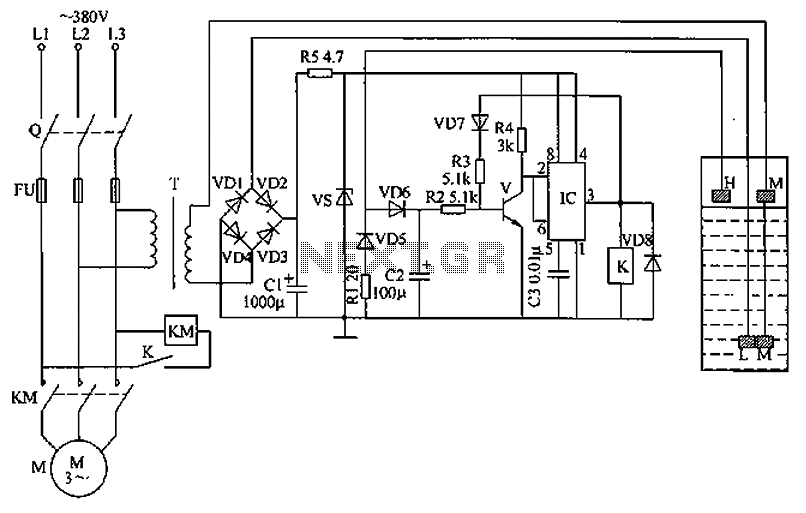
The circuit functions as a liquid level automatic controller, comprising a power circuit, a level detection circuit, and a control execution circuit. The power circuit includes a knife switch (Q), fuse (FU), power transformer (T), rectifier diodes (VD1 to...

This circuit is designed for a 40 Watt fluorescent lamp. It operates similarly to a traditional strobe light, but utilizes a fluorescent tube instead. The fluorescent tube remains continuously energized, with both electrodes supplied with electricity. This current causes...

The DR-650 wiring diagram pertains to the Suzuki DR-650, a single-cylinder, dual-sport motorcycle. This wiring diagram includes a color code for the wires. The schematic diagram provides complete connections for various components, such as the speedometer, lights, CDI unit,...

This section describes the components of the receiver, which includes the post-mixer amplifier, variable crystal filter, intermediate frequency (IF) amplifier, product detector, local oscillator, receiver muting, and audio amplifier. The transmit section features the local oscillator, transmit single balanced...

This perspective is not entirely incorrect, as the functioning of FM detectors is often considered enigmatic. The ratio detector is used to understand its operation, but without... FM detectors are critical components in communication systems, particularly in frequency modulation (FM)...
This example describes a metal detector that employs a PLL (phase-locked loop) digital integrated circuit, the MCl4046. It emits an alarm signal upon detecting metal objects and can identify the type of detected material based on the current meter's...