
Ratio Detector for FM Demodulation
FM detectors are critical components in communication systems, particularly in frequency modulation (FM) applications. The operation of these detectors, while sometimes perceived as complex, can be understood through the examination of their underlying principles and components.
A ratio detector is a specific type of FM detector that converts frequency variations in an incoming signal into amplitude variations. This process typically involves several key elements: a diode, a low-pass filter, and a phase-locked loop (PLL). The incoming FM signal is first fed into the diode, which rectifies the signal and allows for the extraction of the envelope. This envelope reflects the instantaneous frequency changes of the FM signal.
After rectification, the low-pass filter smooths the rectified signal, effectively removing high-frequency components that are not relevant to the desired output. The output from the low-pass filter is then analyzed to determine the amplitude variations that correspond to the original frequency modulated signal.
The ratio detector is particularly valued for its ability to provide a stable output even in the presence of noise, making it suitable for various applications, including radio receivers and audio broadcasting systems. Understanding the operation of these detectors is crucial for engineers designing communication systems, as it allows for the optimization of signal processing and reception quality.
In summary, the ratio detector serves as an essential tool in demodulating FM signals, translating frequency changes into usable amplitude variations, while maintaining robustness against noise interference. This functionality is foundational in many modern communication technologies.This view is not far from wrong because the operation of FM detectors is widely regarded as mysterious. The ratio detector to find out how it works, without.. 🔗 External reference
Related Circuits
This circuit is a metal detector designed to detect large metallic objects at depths ranging from 2 to 3 meters, depending on the size of the object and the type of soil. The construction is straightforward, making it accessible...
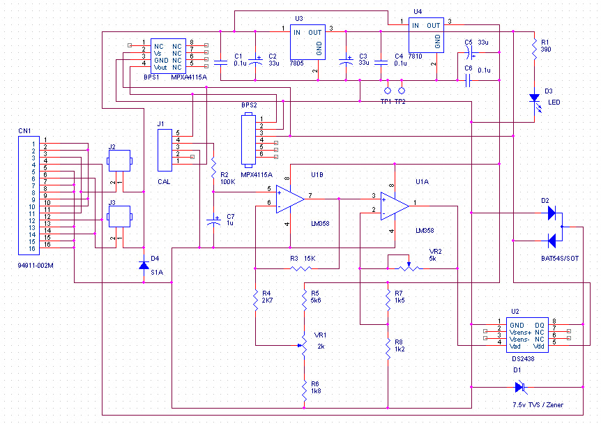
The resolution of the barometric pressure is approximately 0.00417 inHg (0.0139 kPa) within a pressure range of 31.0 to 28.0 inHg (105.0 to 95.0 kPa, or 1050 to 950 mb or hPa). Higher resolutions can be achieved with a...
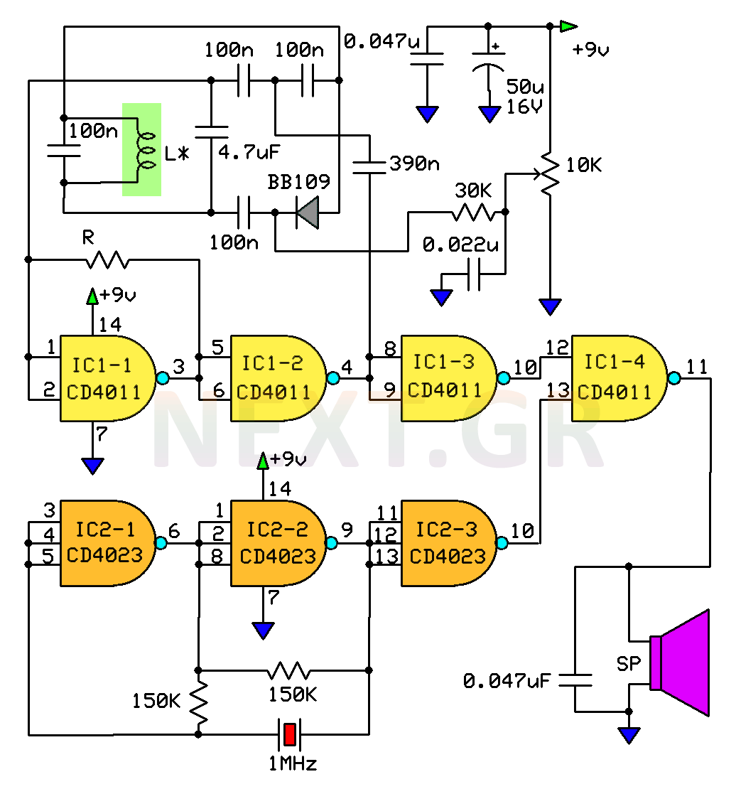
The circuit described here is that of a metal detector. The operation of the circuit is based on superheterodyning principle which is commonly used in superhet receivers. The circuit utilises two RF oscillators. The frequencies of both oscillators are...
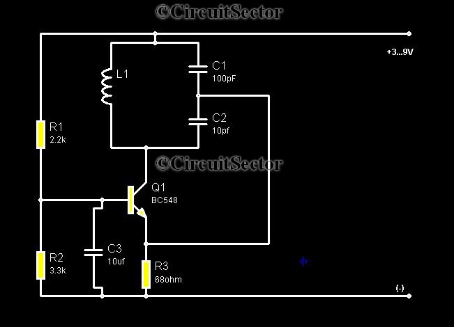
Metal detectors are typically complex devices that often incorporate expensive components, making DIY metal detector circuits uncommon. However, this metal detector hobby circuit can be built using only a few components, such as a BC548 transistor and a standard...
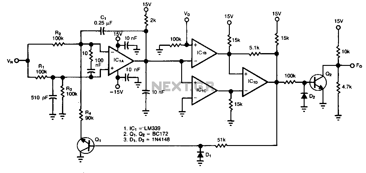
The circuit accepts two positive voltage inputs, VN and Vv, and provides a TTL-compatible output pulse train whose repetition rate is proportional to the ratio VN/V0. The full-scale output frequency is approximately 100 Hz, and the linearity error is...
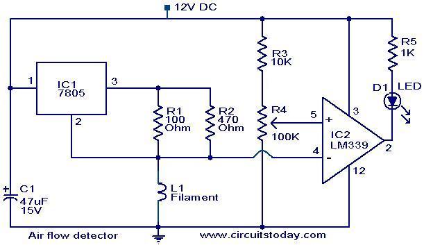
The filament of an incandescent bulb serves as the sensing component of the circuit. When there is no airflow, the resistance of the filament is low. In contrast, when airflow is present, the resistance decreases because the moving air...