
Snore Alarm

The snore alarm circuit is designed to detect snoring sounds and activate a vibrating motor to gently rouse the snorer without disturbing others in the vicinity. The core components of the circuit include a microphone for sound detection, an operational amplifier for signal conditioning, a comparator for threshold detection, and a motor driver to power the vibrating motor.
The microphone picks up the sound of snoring, converting the acoustic signals into electrical signals. These signals are then fed into an operational amplifier configured in a non-inverting mode to amplify the sound levels. The amplified signal is subsequently sent to a comparator circuit, which has a variable reference voltage set by a potentiometer to adjust the sensitivity of the snore detection. When the amplified signal exceeds this threshold, the comparator outputs a high signal.
This output is then used to trigger a motor driver circuit, which can be a simple transistor switch or a dedicated motor driver IC. The motor driver activates the small motor housed within the 35mm film case, causing it to vibrate. This vibration is sufficient to wake the snorer while keeping the noise level minimal.
Additionally, the circuit includes a level control feature that allows the user to adjust the sensitivity of the microphone, ensuring that only sounds above a certain level will activate the motor. The peak display indicator provides visual feedback on the sound levels detected, helping the user gauge the effectiveness of the settings and adjustments made.
The entire assembly is compact and can be discreetly placed under a mattress or pillow, making it an unobtrusive solution for managing snoring without disturbing others in the same household. The combination of adjustable thresholds, visual indicators, and vibration-based alerts makes this snore alarm an innovative approach to a common sleep disturbance.The idea behind this snore alarm, is just to rouse the snorer, not the entire household. To wake the sleeper, vibration is used, not an audible alert. The vibration is provided by a small motor housed in a small 35mm film case, which can be placed under the sleepers mattress or pillow. This circuit has a level control and peak display indicator, a variable trigger threshold and trigger indication.
🔗 External reference
Related Circuits

The circuit was designed to create an alarm system that alerts a sleeping person to prevent snoring by utilizing a vibrator instead of an audio alert. The circuit operates on the principle of detecting snoring sounds through a microphone or...

An ultra-simple circuit of the tilt sensor alarm can be fabricated using readily available, inexpensive components. The circuit operates as a true transistor-based design. The tilt sensor alarm circuit utilizes a tilt sensor, which is a device that detects the...

The IC 555 Light Alarm (Sun Up Alarm) is a circuit designed to emit a loud alarm at dawn, particularly beneficial for individuals who struggle to wake up even with a traditional alarm clock. The circuit can be modified. The...

Have you ever observed the stairs to an upper story in your house transform into a waterfall? Or perhaps you returned home to find your aquarium fish attempting to swim across the carpet? For your sake, it is hoped...

The tone generated by a 555 oscillator can be activated by heat or light, which causes Q1 to conduct transistor Q2 (TIP 3055). Q2 (TIP 3055) functions as an audio amplifier and speaker driver. The circuit utilizes a 555 timer...
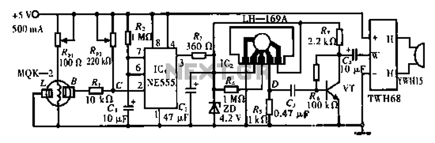
The circuit operates using the MQK-2 gas sensor, which detects the presence of combustible gases or smoke through surface adsorption. When gas is detected, the inter-electrode resistance (BL) decreases significantly. This change in resistance affects the voltage at node...