
Serial Servo Controller with Arduino
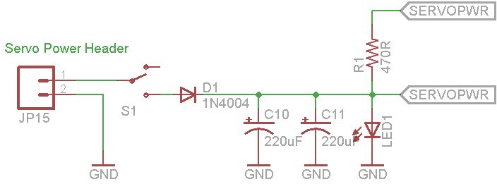
The described application utilizes an Arduino microcontroller, which serves as the central processing unit for controlling multiple servo motors. The architecture includes a dedicated power supply board to ensure that the servos receive adequate voltage and current without affecting the Arduino's performance. This separation is critical, as servos can draw significant current, especially when starting or under load, which could lead to voltage drops affecting the Arduino.
The firmware component is programmed to handle the communication between the Arduino and the servos. It implements a serial communication protocol that allows for real-time control of servo positions, enabling users to send commands to adjust the angles of each servo. The firmware also includes functionality to store and retrieve predefined positions, allowing for complex movements and sequences to be executed with ease.
The software interface developed for this application allows users to interact with the firmware through a user-friendly graphical interface. Users can issue commands to the Arduino, set servo positions, and initiate playback of recorded sequences. The software's reliance on the .NET framework ensures compatibility with a wide range of Windows operating systems, enhancing accessibility for users.
Overall, this application provides a robust and flexible solution for controlling multiple servos, making it suitable for various robotics and automation projects. The combination of reliable hardware design, efficient firmware, and intuitive software interface facilitates comprehensive control over servo motors, paving the way for innovative applications in the field of electronics and robotics.I`m going to show you how to use your Arduino to control up to 12 servos at once with minimal jitter. Using a simple serial interface you can control the position of up to 12 servo channels. Up to 10 snapshot positions can be saved and played back at any time. Start up values for each servo can be saved as well. There are two major parts to the ap plication. The first part I will discuss is the firmware and hardware. This includes the Arduino and another board we will use to supply power to the servos. It`s important to isolate the servo power supply from the microprocessor power in case the servos need more current than the battery can supply (imagine all 12 servos stalling at once). If the power supplies are the same you could have a brownout condition on your microprocessor depending what type of power supply you are using.
I will also show you the firmware required to run this application on the Arduino. In the second part I will discuss some simple software that will allow you to control the firmware through serial commands. This software provides an interface to the Arduino firmware to control the servos, save servo start up positions, even record a series of positions, or frames, (of all channels saved at once) to playback in sequence when desired.
The software is. Net based so make sure you have the latest. Net framework installed. I will be supplying an installer and source code. 🔗 External reference
Related Circuits

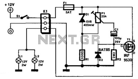
A servo tester circuit has been built as shown. The only observable action is for the servo to twitch when the power is switched on. There is no clear reason for its failure to operate correctly. Suggestions for troubleshooting...
It is assumed that most readers are considerate drivers who do not activate their rear fog lights when closely followed by other vehicles. Following drivers may mistakenly think that the vehicle is braking, leading them to react by applying...
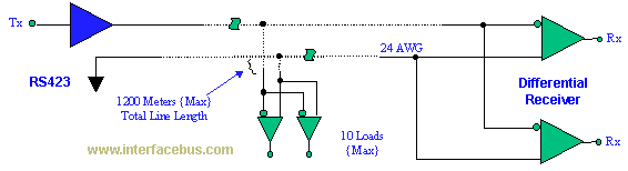
The EIA/TIA-423 Unbalanced (Single-Ended) interface specifies a single, unidirectional driver with multiple receivers (up to 10). It outlines the electrical characteristics of the unbalanced voltage digital interface circuit, typically implemented in integrated circuit technology, which can be used for...
The circuit is completely conventional, and has been around almost forever in one guise or another. Similar circuits were used in the valve (tube) era, so there is nothing new about it. The circuit has already been published on...
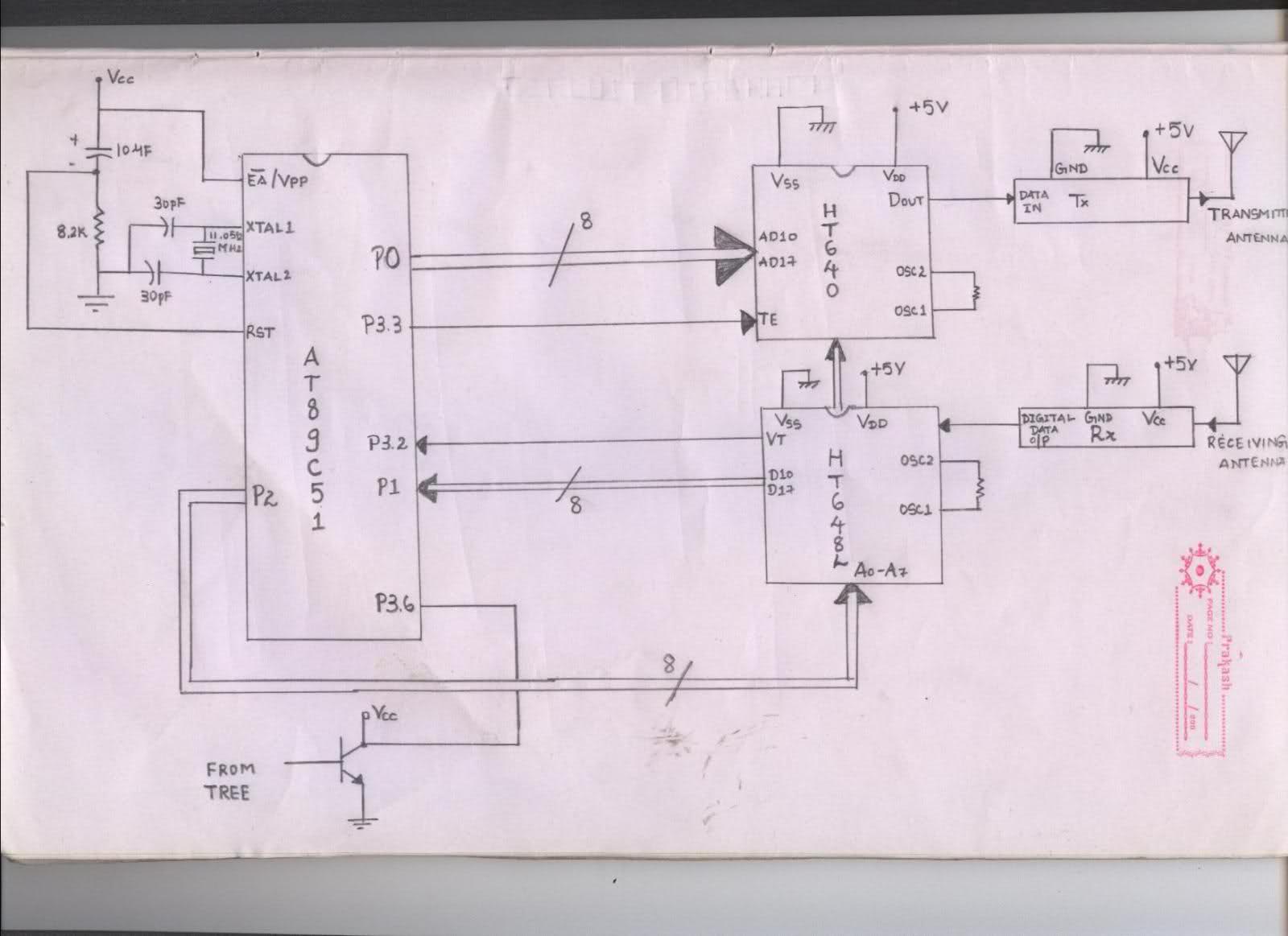
The issue arises when connecting the 8051 microcontroller to the HT640 encoder; the data sent is not received at the receiver. However, when the connections to the 8051 are removed, the transmission functions perfectly. This indicates that manual RF...
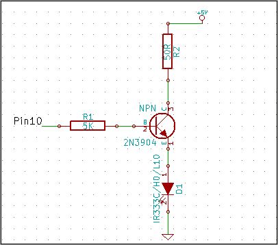
The 2N3904 is an NPN transistor. When observing the flat face of the transistor, the left lead is the Emitter (pin 1 in the schematic), the middle lead is the Base (pin 2 in the schematic), and the right...