
Light Controlled Relays
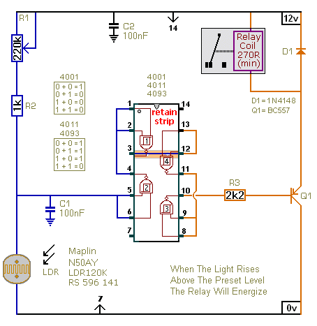
The described circuit consists of two light-sensitive relay control circuits, each utilizing a Light Dependent Resistor (LDR) to detect ambient light levels. The first circuit activates the relay when the light intensity exceeds a predetermined threshold, while the second circuit activates the relay when the light intensity drops below this threshold.
Both circuits are designed similarly, with the primary distinction being the orientation of the transistor used in each circuit. This bipolar junction transistor (BJT) configuration allows for the switching of the relay based on the light levels detected by the LDR. The LDR's resistance decreases with increasing light levels, which allows for the modulation of the voltage at the transistor's base, effectively controlling the relay's state.
The circuit operates by monitoring the voltage levels at pins 5 and 6, which are critical for determining the relay's activation state. The selection of the LDR is flexible, as any LDR can be used satisfactorily; however, the resistance value of R1 may need adjustment to fine-tune the sensitivity and range of the light detection. This adjustment will ensure that the circuit accurately responds to the specific light conditions required for the application.
It is crucial to note that the on-board relay should not be used for switching mains voltage due to insufficient isolation between the relay contacts and the low-voltage components on the board. For applications requiring mains voltage switching, it is recommended to use an appropriately rated relay mounted in a secure location, ensuring compliance with safety standards and preventing potential hazards associated with electrical isolation.The first circuit energizes the relay when the light rises above the preset level. The second circuit energizes the relay when the light falls below the preset level. The two circuits are practically identical. The only difference between them is the polarity of the transistor. The value of the LDR is not critical. The important thing is the voltage on pins 5 & 6. Any value LDR should work satisfactorily. But you may need to change the value of R1 - to achieve the desired range of adjustment. Do not use the "on-board" relay to switch mains voltage. The board's layout does not offer sufficient isolation between the relay contacts and the low-voltage components. If you want to switch mains voltage - mount a suitably rated relay somewhere safe - 🔗 External reference
Related Circuits
This circuit is designed around a 555 timer and utilizes a minimal number of components. Due to its simplicity, it can be easily constructed and operated by beginners. The circuit leverages the 555 timer IC, which is a versatile and...
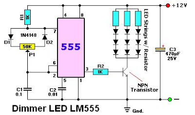
The LM555 timer IC can be utilized in various electronic projects, including the creation of an analog timer. According to the datasheet, the LM555 is versatile and can be adjusted to set timers based on specific requirements. The schematic...
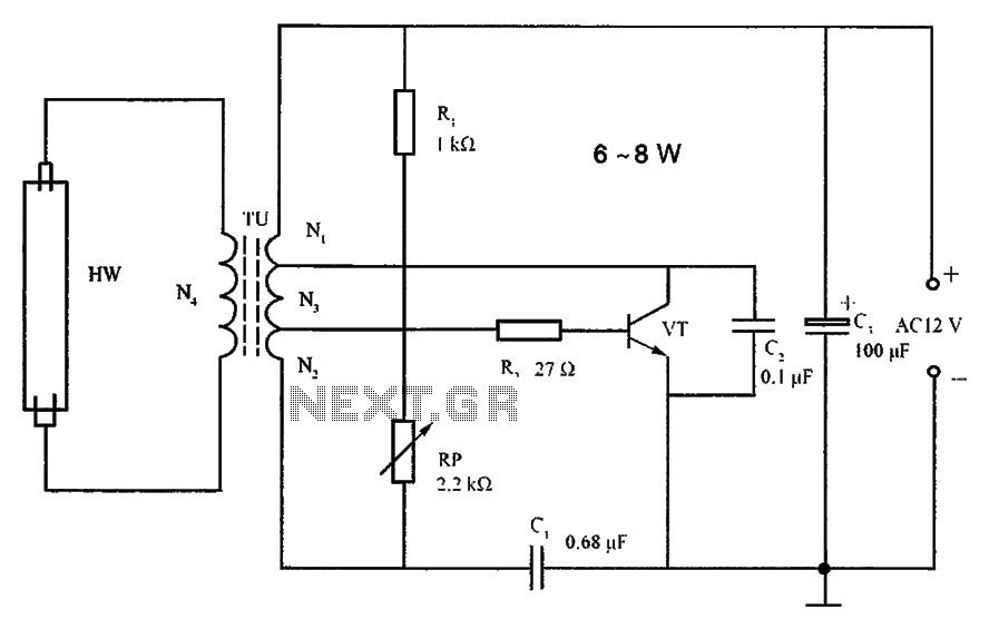
The lighting inverter circuit is designed for 6 to 8W fluorescent tubes. This circuit is appropriate for powering fluorescent tube circuits within the specified wattage. The parameters for the circuit are indicated in the accompanying figure. When utilizing a...
I have received several emails asking how to connect up some lights so that when the phone rings, they flash. This is very useful in a situation where there is lots of noise and it is impossible to hear...
This circuit is a stable frequency counter with an accuracy of 5 significant digits. It operates within a frequency range of 0 to 30 MHz and has an input sensitivity greater than 100 mV. The probe connects to the...
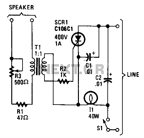
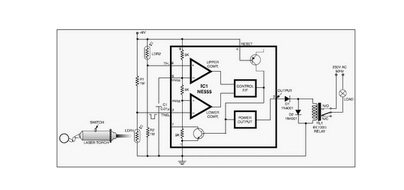
The lights appear to synchronize with the music. Line-voltage lamps rated between 40 to 100 watts function effectively. The current for the lamp is controlled by a silicon-controlled rectifier (SCR). When low-level audio signals are present across transformer T1,...