
Ringing Phone Light Flasher
To create a phone ring indicator circuit that activates lights when a phone rings, a simple schematic can be designed using a combination of components including a relay, diodes, resistors, and zener diodes. The circuit's primary function is to detect the ringing voltage from the telephone line and use it to energize a relay that will, in turn, power the lights.
The circuit begins with a connection to the telephone line. When the phone rings, it generates an AC ringing signal typically around 20Hz to 30Hz at a voltage of 90V to 120V. This signal can be dangerous; thus, it is crucial to ensure proper isolation and voltage handling throughout the design.
A suitable method to detect the ringing signal involves using a resistor divider network to step down the voltage to a manageable level. Following this, a diode (D1) can be employed to rectify the AC signal, allowing only the positive half-cycles to pass through. A zener diode (D2) is then used to clamp the voltage to a safe level, preventing damage to subsequent components. The choice of zener voltage should be appropriate for the following components, ensuring they operate within their specified limits.
The output from the zener diode can then be fed into the control circuit of a relay. A solid-state relay (SSR) is preferred due to its ability to handle high voltages without mechanical wear. However, if a mechanical relay is used, it is essential to consider the potential for arcing across the contacts, which can lead to premature failure. A snubber circuit may be added across the relay contacts to mitigate this risk.
When the relay is energized, it closes the circuit for the lights, causing them to flash in response to the phone ringing. The lights can be connected to the relay's output, ensuring that they operate at the desired voltage and current ratings.
It is imperative to ensure that all components are rated for the voltages and currents they will encounter, particularly when interfacing with the telephone line. Proper insulation and safety precautions should be observed to prevent accidental contact with high voltages.
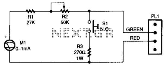
In summary, this circuit provides a practical solution for alerting individuals in noisy environments when a phone is ringing, utilizing simple electronic components and principles to achieve effective visual signaling.I have received several emails asking how to connect up some lights so that when the phone rings, they flash. This is very useful in a situation were there is lots of noise and it is impossable to hear the phone, such as a workshop.
Here is such a device. # You may need to use a lower voltage zener for D1 and D2. # You can use a regular relay instead of a solid state relay, but the arcing accross the contacts may destroy it pretty quickly. # Be very sure that you have not accidentally connected 120V 🔗 External reference
Related Circuits

Children today often possess a wide array of toys available in stores. For those with a son or grandson who has a collection of toy cars, a handmade gift such as a set of traffic lights would be greatly...

Flight Computer V1.0: B1 PC Board U1 80C32 microprocessor U2 27C256-12 32Kx8 ROM - 120nS "V2.1" U3 74HC373 U4 LM340T-5 5V regulator (may also be a 7805 part) U5 43256-15 32Kx8 RAM - 150nS U6 74HC00 T1-T4 2N6045 or...
When the switch SI is pressed, the silicon-controlled rectifier (SCR) is activated, connecting LED1 and resistor R1 across the telephone line. This action causes the line voltage to drop to approximately 20 volts, which maintains the connection to the...
While conversing with a distant subscriber on the telephone, it is common to experience frustration due to faint audio that is barely intelligible. To address this issue, an inexpensive amplifier circuit is proposed. This circuit can be easily assembled...
This is a simple LED flasher using two 2N3904 transistors. Classic astable multivibrator using 2 transistors. Transistor is not critical. Try these: 2N4401, 2N2222, NTE123A, NTE123AP, NTE159, TUP/TUN and those in your junk box, you may find that most...
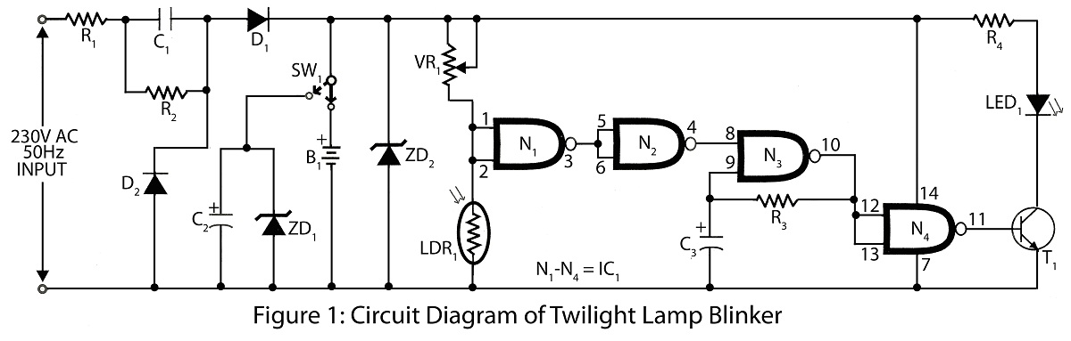
Twilight Lamp Blinker circuit can be constructed using a Light Dependent Resistor (LDR) and a single integrated circuit (IC). The circuit diagram includes a parts list for various projects utilizing the LDR and additional components. The Twilight Lamp Blinker circuit operates...