
Light Dependent Resistor
The Light Dependent Resistor (LDR) circuit is a vital component in various applications where automatic light detection is required. The fundamental operation relies on the photoconductive properties of cadmium sulfide, allowing it to effectively sense light levels. In practical circuit designs, the LDR is typically connected in a voltage divider configuration with a fixed resistor or a potentiometer to establish a reference voltage.
When designing the circuit, the choice of resistor values is crucial for determining the sensitivity and response time of the LDR. The fixed resistor should be selected based on the expected ambient light conditions to ensure that the voltage drop across the LDR can effectively trigger the transistor at the desired threshold. For instance, in a darkness-activated circuit, the fixed resistor should be chosen to provide a suitable biasing condition for the transistor when the LDR is in a high-resistance state (darkness).
In addition, the transistor selected for the circuit should be capable of handling the expected current load for the output device, such as an LED or relay. Commonly used transistors for low-power applications include the 2N3904 or BC547, while higher power applications may require MOSFETs or relays for switching larger loads.
The circuit layout should also consider noise immunity and stability, especially in outdoor applications where environmental factors may introduce interference. Using bypass capacitors across the power supply and placing the LDR in a shielded enclosure can help mitigate these effects.
In summary, the LDR circuit is not only simple to construct but also versatile, making it suitable for various applications ranging from basic light detection to more complex automated systems. Proper component selection and circuit design will ensure optimal performance and reliability in the intended application.A Light Dependent Resistor (aka LDR, photoconductor, photoresistor, or photocell) is a component used commonly in electronics which has a resistance which decreases as the intensity of the light hitting its surface increases and visa versa. A typical light dependent resistor is pictured above together with (on the right hand side) its circuit diag
ram symbol. The vast majority of LDRs are made from cadmium-sulphide (CdS), and they are very cheap, but also not very accurate. They are very good for detecting changes in light levels and determining if it is `dark` or `light`, but without individual calibration they not suitable for accurately measuring light levels.
Pictured below is a typical light dependent resistor. It has two wire leads which terminate in the face of the light detector - the two metal dots you see are the ends of those electrodes. The main body of the light detector component is made of ceramic - an excellent insulator. On the face of the ceramic a thin strip of cadmium sulphide is coated in a zig-zag pattern (to maximise the length of the strip while keeping the component small) which is connected at each end to an electrode.
The front face is then coated in clear plastic, epoxy, glass, or similar. Cadmium-sulphide is a high resistance semiconductor, and is chosen for light detectors as it gives the same spectral response as the human eye - i. e. it `sees`/responds to the same range of wavelengths of light that we can see. Specifically, cadmium-sulphide is a photoconductive material. That means that photons of light hitting it with sufficient energy will release electrons from their atomic bonds.
When a negatively charged electron is freed by a photon of light, it leaves behind a positively charged `hole`. When a voltage is applied across the two wire leads of the light detector, the free electron moves one way along the CdS strip, and the free `hole` moves the other way; and it is this movement of charge which is electricity flowing through the light detector.
The higher the light intensity, the more photons of light are hitting the CdS strip, the more electron-hole pairs are generated, the more electricity can flow through the light detector, and so the lower the resistance of the light detector (i. e. it is easier for electricity to flow through the light detector when the light intensity hitting it is high).
Different LDR`s have different specifications, however the mini LDR`s we sell in the REUK Shop are fairly standard and have a resistance in total darkness of 1 MOhm, and a resistance of a couple of hundred Ohm in bright light. Light dependent resistors are a vital component in any electric circuit which is to be turned on and off automatically according to the level of ambient light - for example, solar powered garden lights, and night security lighting.
An LDR can even be used in a simple remote control circuit using the backlight of a mobile phone to turn on a device - call the mobile from anywhere in the world, it lights up the LDR, and lighting (or a garden sprinkler ) can be turned on remotely! There are two basic circuits using light dependent resistors - the first is activated by darkness, the second is activated by light.
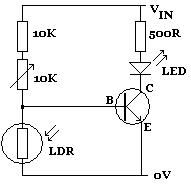
The two circuits are very similar and just require an LDR, some standard resistors, a variable resistor (aka potentiometer), and any small signal transistor In the circuit diagram above, the LED lights up whenever the LDR is in darkness. The 10K variable resistor is used to fine-tune the level of darkness required before the LED lights up.
The 10K standard resistor can be changed as required to achieve the desired effect, although any replacement must be at least 1K to protect the transistor from being damaged by excessive current. By swapping the LDR over with the 10K and 10K variable resistors (as shown above), the circuit will be activated instead by light.
Whenever sufficient light falls on the LDR (manually 🔗 External reference
Related Circuits
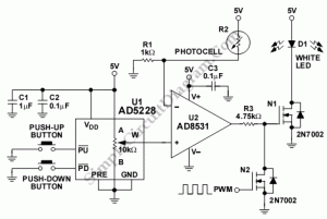
The following circuit illustrates the use of the AD8531 integrated circuit for the automatic control of LCD panel backlighting. Features include the ability to compensate for aging effects. The AD8531 is a precision operational amplifier that is well-suited for applications...
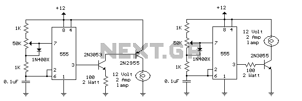
This circuit is designed to dim lights with a maximum capacity of approximately 350 watts. It employs a standard TRIAC circuit configuration, which has been observed to generate minimal heat during operation. It is important to note that this...
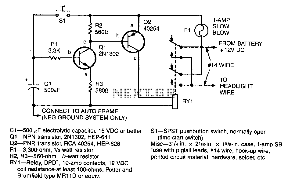
When the driver presses pushbutton switch S1, timing capacitor C1 charges to 12 V, activating transistor Q1, which in turn drives power transistor Q2 into conduction. This action energizes the relay, which has its contacts connected in parallel with...
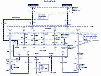
The section of the 1996 Ford Windstar wiring diagram includes details on power distribution, common connections, rear circuits, ignition systems, the fuse panel, battery connections, instrument illumination, radio wiring, left rear speaker connections, remote headphone module, solid-state components, and...
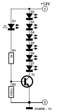
This simple and inexpensive circuit is not limited to Christmas. It consists of two resistors, a small-signal transistor such as a BC547, one flashing LED, and a string of standard LEDs. The flashing LED functions as an oscillator, turning...
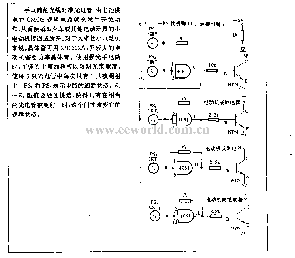
The light from a flashlight is directed at a phototube, which activates a CMOS logic circuit powered by a battery. This circuit controls the switching action to turn the motor of a model train or other electric toys on...