
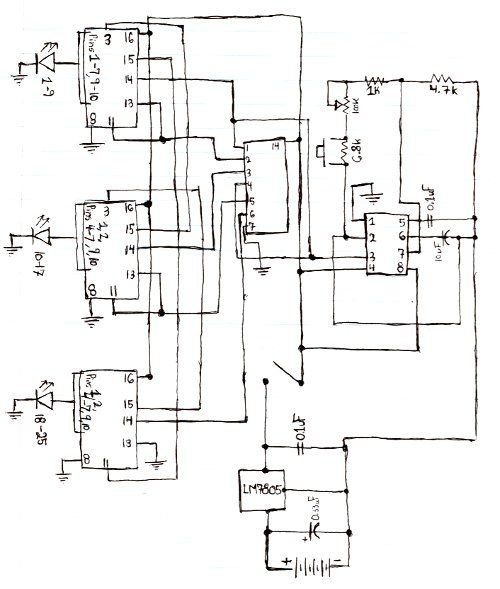
Light-Dependent Sensor For Multiple Inputs Circuit

The circuit typically consists of an LDR connected in a voltage divider configuration with a fixed resistor. The output voltage from this divider is fed into a comparator or microcontroller input. When the ambient light level is above a certain threshold, the voltage remains below the reference level set at the comparator. In this state, the output remains low, and the alarm remains silent.
When the light is interrupted—such as by an object passing in front of the sensor—the resistance of the LDR increases, causing the voltage at the comparator input to rise above the reference level. This change triggers the output of the comparator to switch states, activating the alarm.
To enhance the circuit's reliability, hysteresis can be introduced by adding a feedback resistor from the output of the comparator back to the non-inverting input. This prevents the alarm from chattering due to minor fluctuations in light levels. The alarm can be a simple piezo buzzer or a more complex sound module, depending on the application requirements. Additionally, a power supply circuit may be included to ensure stable operation, along with a reset mechanism to allow for manual or automatic reset of the alarm after it has been triggered.
Overall, this light-dependent sensor circuit is effective for applications such as security systems, where detecting the interruption of light can indicate unauthorized access or movement in a designated area. This light-dependent sensor uses LDRs to detect the presence or absence of light. As long as the light source striking the LDRs remains constant, the alarm does not sound. But when the light is interrupted, the alarm is triggered. 🔗 External reference
Related Circuits
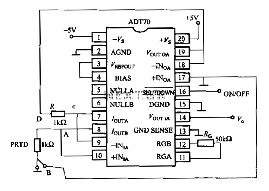
The AD170 basic electrical parameters include a temperature coefficient of 25 ppm/°C and a temperature measurement accuracy of ±1°C, with a maximum temperature range of -200°C to +100°C. The power supply required is +5V or -5V, and the operating...
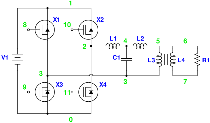
Magic Sinewave Analysis using SPICE and a Simple Inverter Circuit. This document discusses the analysis of a sinewave signal generated by a simple inverter circuit using SPICE simulation software. The inverter circuit is designed to convert a DC input voltage...
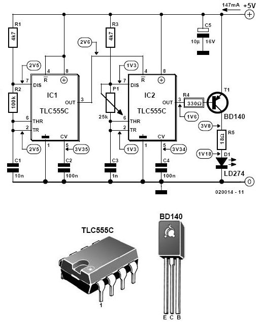
Here is the schematic for the circuit. Solder all the components onto a perfboard. The drawings may not be very clear. Essentially, the 555 timer generates a pulse. The circuit utilizes a 555 timer IC configured in astable mode, which...

Below is the circuit diagram for the Theremin music instrument effect. A guitar or instrument amplifier is an ideal companion for the Theremin, allowing for bass or treble boost as desired, as well as fuzz (distortion) or reverberation if...

This circuit utilizes a 4049 integrated circuit (IC) to control a 2N2222 switching transistor. The transistor, in turn, drives a piezo transducer known as crystal 1. The circuit design begins with the 4049 IC, which is a hex inverter capable...
This infrared alarm barrier is designed to detect individuals passing through doorways, corridors, and small gates. The transmitter emits an invisible beam of infrared light. When this beam is interrupted by a person, a buzzer connected to the receiver...
Warning: include(partials/cookie-banner.php): Failed to open stream: Permission denied in /var/www/html/nextgr/view-circuit.php on line 713
Warning: include(): Failed opening 'partials/cookie-banner.php' for inclusion (include_path='.:/usr/share/php') in /var/www/html/nextgr/view-circuit.php on line 713