
Light dimmer

This dimmer circuit operates by utilizing a thyristor to control the phase angle of the AC voltage supplied to the incandescent bulb. The double delay circuit is crucial for achieving a smooth transition in brightness levels, allowing for fine adjustments from completely off to fully on. The two-terminal connection design facilitates easy integration into existing switch boxes, thus simplifying installation without requiring extensive modifications to the electrical system.
The use of a thyristor such as the KT505 provides reliable performance, with a maximum current rating of 1A, which supports a load capacity of up to 200W. This makes it suitable for most standard incandescent bulbs used in residential lighting applications. The dimmer's ability to reduce brightness to zero enhances its functionality, allowing users to control lighting levels without the necessity of a separate switch, thereby contributing to energy savings and extended bulb life.
Capacitors in this circuit are required to handle low voltage, and the use of electrolytic capacitors is recommended due to their compact size and efficiency in filtering applications. However, caution must be exercised as the circuit is connected to mains voltage, which poses a significant safety risk. It is imperative that users adhere to safety protocols, including disconnecting the circuit from the mains supply before replacing bulbs or performing any maintenance.
The inclusion of a potentiometer with a plastic shaft is essential for user safety, as it minimizes the risk of electric shock during operation. Overall, this dimmer circuit design is effective for controlling incandescent lighting, providing both functionality and ease of use while emphasizing the importance of safety precautions in its operation.This dimmer is used to adjust the brightness of incadescent bulbs (dimming) from zero to maximum. Regulation from zero is achieved using double delay circuit. The circuit is two-terminal connected and so it can be installed into switch box without modifying the installation. To regulate the phase angle the dimmer uses ordinary thyristor (SCR) such as KT505 (or KT504, KT508, etc. ). The maximum current is 1A, so you can connect up to 200W load. Brightness can be dimmed to zero, so there is no need use the switch. Capacitors are just at the low voltage, so you can use electrolytic ones. Warning - the circuit is electrically connected to the mains - deadly voltage. The light bulb must not be replaced under voltage, even when the dimmer is set to minimum. Before replacing the bulb or handling the circuit you must disconnec it from mains. The potentiometer must have a plastic shaft. 🔗 External reference
Related Circuits
All files are found using legitimate search engine techniques. This site does not condone hacking into sites to create the links it lists. It is assumed that all links found on the search engines used are obtained legally and...
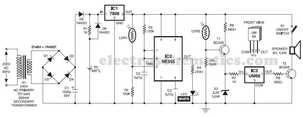
This musical light alarm circuit is very simple and uses only seven components, including a light-dependent resistor (LDR) and a 3.6V battery or three 1.2V rechargeable batteries. The well-known UM66 is utilized as the sound generator, providing a pleasant...
These relatively simple circuits can be used to transmit information across a small distance. The information typically used includes music from a radio, iPod, or CD player; a microphone and amplifier can also be utilized. People frequently transmit information...
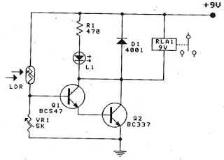
The sensors used are silicon phototransistors and Cadmium Sulfide (CdS) photocells. Both of these sensors allow less current to flow when they are dark than when lighted. Phototransistors change their conductance while photocells change their resistance depending on the...
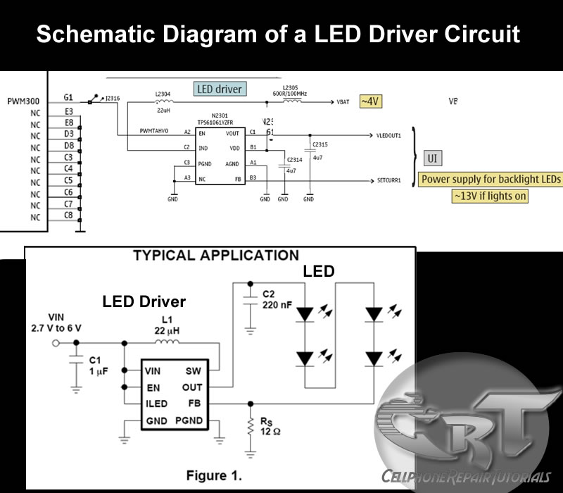
An LED (light-emitting diode) is utilized to illuminate keypad keys and LCD screen displays on all mobile phone handsets. It is controlled by the voltage or current drawn at its terminals. In the schematic diagram, the LEDs are driven...
It allows car headlights to flash on and off simultaneously or alternately. Components: 555 IC, transistor, resistor, relay, polarized capacitor. The circuit utilizes a 555 integrated circuit (IC) in a monostable or astable configuration to control the flashing of car...
Warning: include(partials/cookie-banner.php): Failed to open stream: Permission denied in /var/www/html/nextgr/view-circuit.php on line 713
Warning: include(): Failed opening 'partials/cookie-banner.php' for inclusion (include_path='.:/usr/share/php') in /var/www/html/nextgr/view-circuit.php on line 713