
lighting leds
LED lighting circuits are commonly employed in various applications, including residential, commercial, and automotive lighting. In designing an LED circuit, careful attention must be paid to the power supply voltage, the number of LEDs in series, and the current limiting method to ensure the longevity and reliability of the LEDs. For instance, when designing a circuit for a 12-volt battery-operated system, using three LEDs in series with a 50-ohm resistor ensures that the voltage drop across the LEDs and the resistor is managed effectively.
In higher voltage applications, such as 115VAC, additional considerations must include the use of rectifiers to convert AC to DC, filtering capacitors to smooth out the output, and possibly a switching regulator to maintain a constant current through the LEDs. It is essential to ensure that all components are rated appropriately for the voltages and currents involved, including the use of heat sinks for high-power applications to dissipate excess heat generated by the LEDs and resistors.
Overall, a thorough understanding of LED characteristics, circuit design principles, and safety measures is critical for the successful implementation of LED lighting systems.For longest life, we recommend you run them at 20-25 milliamps (ma). HOWEVER, in our LED flashlight conversions (and many commercial LED flashlights), the LEDs are run at 50-60ma, twice the rated current. One of our test LEDs ran at 98ma for over 200 hours without damage or appreciable light loss. So go ahead and experiment with running them at over rated current if you are willing to take the risk of a shorter life. In my opinion, a flashlight bulb that lasts 100 hours is a huge improvement and cost saver over the incandescent alternative which gives only 15-20 hours before it dies. You must use some method of limiting current to your strings of LEDs. The easiest is simply using the right number of LEDs for your supply voltage. Each white LED gives a voltage drop of 3. 6 volts. So, for a 115 volt DC light, you could use 32 white LEDs in series (115 / 3. 6 = 32 +/-) with NO current limiting (they will limit themselves by their inherent voltage drop). In reality, though, there are many other circuit design issues you need to look at to build a reliable 115VAC home LED lighting fixture!
We link to a few resources farther down on this page, and you can always Google up `LED lighting circuits` for more information. Reverse polarity will not damage an LED unless the voltage is very high-it simply will not work, and will not pass current through.
However, be sure to check the manufacturer`s rating for the specific LEDs you are using-there are some out there, particularly the latest models, that can be damaged by relatively low reverse voltages. The diagram below shows how the LED package is marked for polarity. The next easiest is a simple resistor. The resistor does consume power, though, but is usually needed since an `ideal` 3. 6 volt source is rarely available. Use Ohms law (Resistance(R)=Voltage(E)/Current(I) to calculate the value and wattage needed: (R=E/I) Each white LED gives a voltage drop of 3.
6 volts. As an example, for a 12 volt light, you can run a maximum of 3 white LEDs in series at full power (3. 6 x 3 = 10. 8 volts drop). Subtract this from your supply voltage of 12 volts to get the additional voltage that must be dropped (in this case, 12 - 10.
8 = 1. 2 volts of additional drop needed). In this case, 1. 2 volts of additional drop /. 025 amps (25 ma) = 48 ohms. Use the next highest value of resistor available, 50 ohms. You must also be sure the resistor can handle enough current. Volts x Amps = Watts; resistors are rated in watts. So in this case, 1. 2 volts x. 025 amps = 0. 03 watts. A 1/4 watt resistor will work fine, but if you run a second string of 3 LEDs in parallel, each string would need its own 50 ohm resistor. It`s important that each string has its own resistor. putting them in parallel with a single resistor is bad practice. This method is cheap and works great, but there`s one problem-voltages in 🔗 External reference
Related Circuits
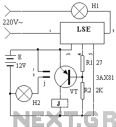
The device circuit operates as illustrated in Figure 11. Power outages are a common occurrence, but in certain situations, maintaining power is critical, such as during ongoing surgeries. The circuit employs a simple design that is fully automated. When...
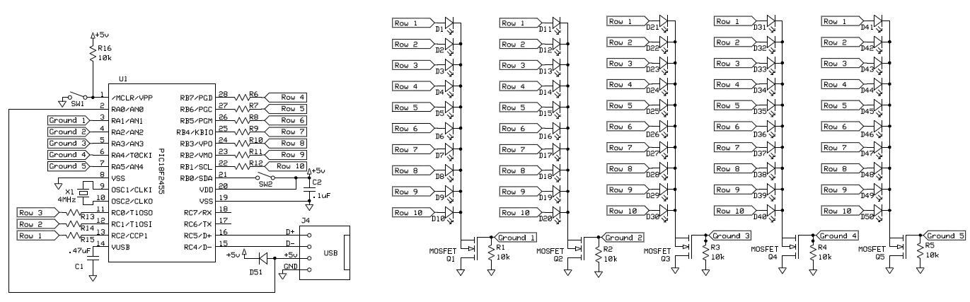
To control 40 LEDs using a single PIC 18F2455 microcontroller, the LEDs were organized into a configuration of four columns, each containing 10 rows of LEDs. Each LED in a column was connected to a separate pin on the...
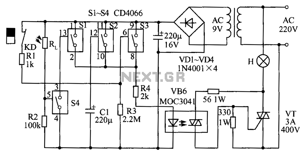
The circuit diagram illustrates a group of four analog electronic circuit switches (S1 to S4). Switches S1, S2, and S3 are utilized in a parallel delay circuit. When the power is activated, resistor R4 drives the triac VT, which...
The last installment in this series (LEDs 102 - Use On Board Trains) concluded with some thoughts on how to turn battery-powered LEDs on and off. This article will explore various options for controlling LEDs and other devices on...
The success or failure of lighting upgrades depends on the quality of components and workmanship. Proper wire routing is essential to prevent insulation chafing. The quality of soldering connections is crucial, as poor solder joints can corrode and fail....
This is a straightforward project suitable for individuals with basic electronic skills. Connecting this circuit to an audio source will cause the LEDs to blink in sync with the rhythm. The described project is an audio-activated LED circuit that visually...