
Electret Mike Preamp Circuit

The described circuit employs an electret microphone, which is a type of condenser microphone that requires a small amount of power to operate. The power source for the circuit is a 1.5-V battery, making it suitable for portable applications where battery life is critical.
The circuit configuration includes components such as CI, which is likely a coupling capacitor, and R3, which is a resistor that plays a role in shaping the frequency response of the microphone signal. The combination of CI and R3 is designed to enhance higher frequency sounds (treble boost) while attenuating lower frequency sounds (bass cut). This feature can be particularly useful in applications where clarity of speech or specific sound characteristics are desired.
If the treble boost and bass cut are not required for a particular application, these components can be omitted from the circuit. This flexibility allows for customization based on the specific needs of the user, making the circuit versatile for a variety of audio applications, such as communication devices, recording equipment, or sound reinforcement systems.
Overall, the circuit provides a simple yet effective means of integrating an electret microphone into electronic projects, with the option to adjust the audio frequency response based on the application requirements. This circuit is suitable for using an electret microphone for many applications. A 1.5-V battery is used. CI and R3provide treble boost/bass cut; they can be eliminated, if desired.
Related Circuits
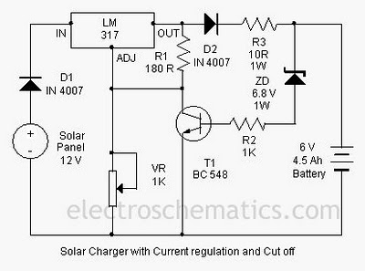
A solar charger circuit is designed to charge lead-acid batteries or nickel-cadmium (Ni-Cd) batteries using solar power. This circuit captures solar energy to charge a 6-volt, 4.5 Ah battery for various applications. It features voltage and current regulation along...
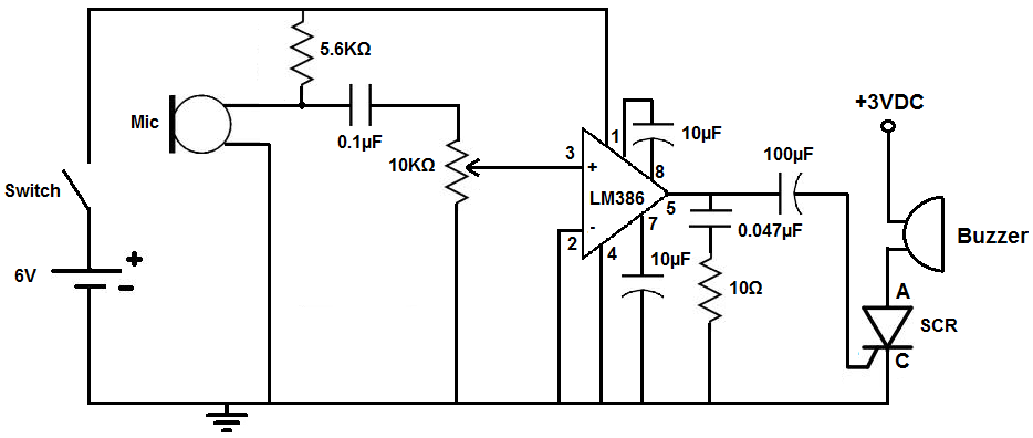
This circuit is designed to activate an alarm when it detects sound above a specified threshold. The alarm serves as a notification for any sound in areas that are typically quiet, such as quiet zones. Under normal quiet conditions,...
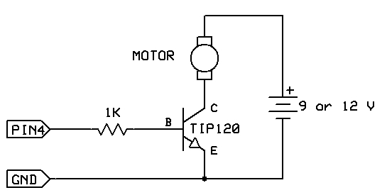
The strategy involves assembling the circuit in stages, testing each component as it is integrated. Once all connections are established and can be controlled or read correctly by the computer, the main program can be developed with assurance that...
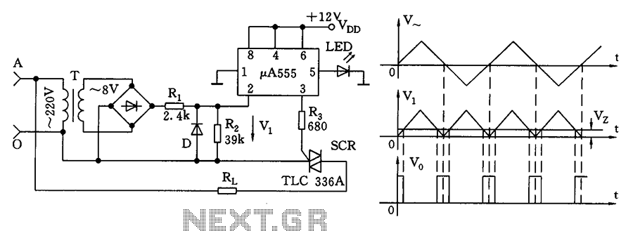
The zero volt switching circuit generates a trigger pulse at the zero crossing of the AC voltage. To facilitate this, the zero crossing of the 555 limit comparator is connected to a single form, with the comparison voltage set...
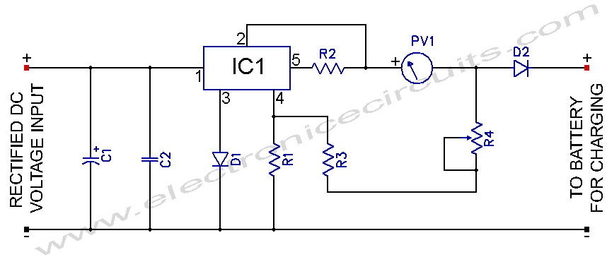
L200 12V Constant Voltage Battery Charger Circuit. This battery charger is based on the L200 regulator IC. The L200 is a five-pin adjustable voltage regulator. The L200 constant voltage battery charger circuit is designed to provide a stable 12V output...
This little guide for every electronics tester would actually have to lie in the toolbox. You can have components such as resistors, capacitors, diodes, etc. of testing. T1 and T2 form a Darlington. Therefore only need a small base...