
light intensity meter
The light intensity meter circuit is designed to measure ambient light levels and can be employed in various applications, including photography, horticulture, and environmental monitoring. The core component of this circuit is typically a light-dependent resistor (LDR), which changes its resistance based on the light intensity it is exposed to.
In a basic configuration, the LDR is connected in a voltage divider arrangement with a fixed resistor. The output voltage from this divider can be fed into an analog-to-digital converter (ADC) for digital processing or directly into a microcontroller for further analysis. The microcontroller can then display the light intensity on an LCD or LED display, providing a user-friendly interface.
The circuit may include additional components such as a potentiometer for calibration, ensuring accurate readings across different light conditions. Powering the circuit can be achieved through a battery or a DC power supply, depending on the intended use case.
For increased functionality, the circuit can be enhanced with features such as data logging, where light intensity readings are stored over time for analysis, or wireless transmission capabilities to send data to a remote monitoring system.
Overall, this light intensity meter circuit serves as a versatile tool for measuring light levels, adaptable to various electronic projects and experimental setups.This simple light intensity meter circuit can be used to determine the intensity of light in a wide variety of electronic projects and experiments.. 🔗 External reference
Related Circuits
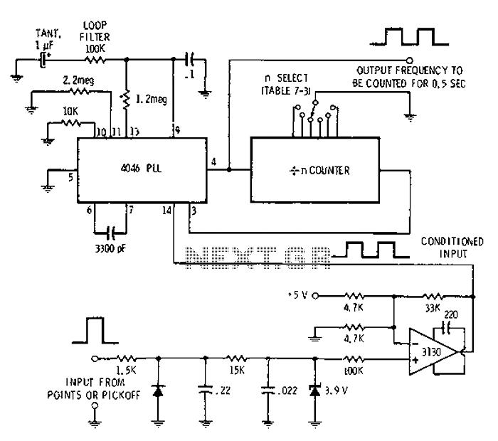
Automotive engine pulse points or other sensors are filtered using the transmission device 3130 CMOS operational amplifier, which functions as a comparator to fulfill the input conditions. The pulse subsequently flows into a 4046 phase-locked loop (PLL) N-counter, which...
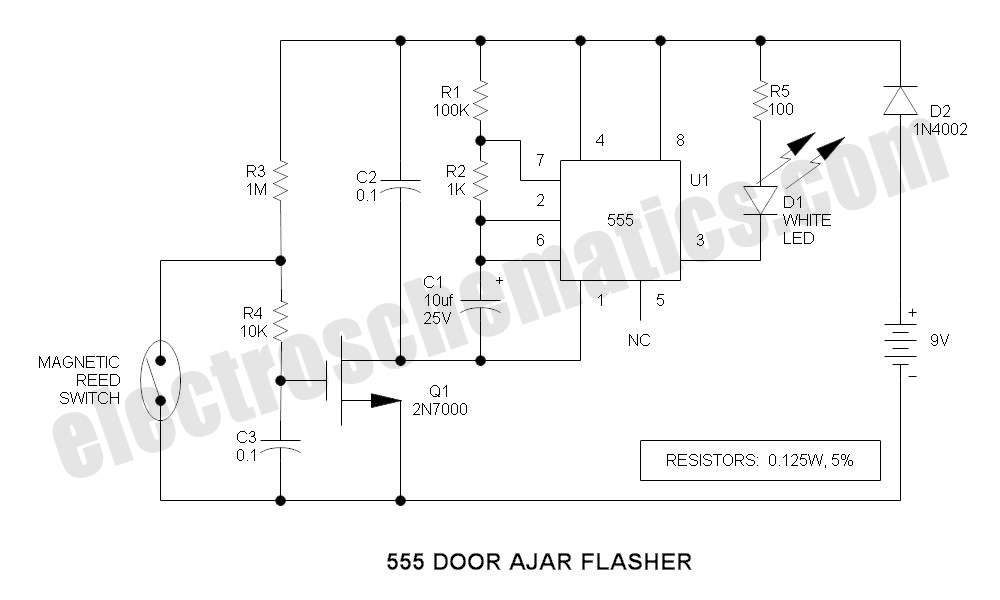
A magnet is positioned on the door, while a magnetic reed switch is installed on the door casing. When the door is closed, the circuit is disabled. When the door is opened, the circuit becomes active. In this circuit design,...
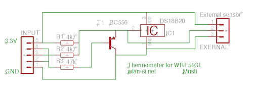
This circuit is a simple dual simplex to half-duplex driver for 1-wire devices. However, it does not function with all devices, as some may draw excessive current. It was specifically designed and tested for the DS18B20+ 1-wire digital thermometer....
A schematic diagram for a broadband QRP SWR metering circuit intended for use in a QRP antenna tuner. The circuit allows the user to press a momentary DPDT switch to observe an LED indicator while adjusting the capacitors of...
The LED current drive is regulated and programmable, which eliminates the need for current-limiting resistors. The integrated circuit (IC) features an adjustable voltage reference and an accurate ten-step voltage divider. The LED current drive circuit is designed to provide precise...
The handheld mini light beam receiver features a small solar cell on the left side, with various components visible on the circuit board through a transparent lid. On the right side, there are sockets for headphones and a crystal...