
vu meter using a lm3915 circuit diagram
The LED current drive circuit is designed to provide precise control over the current flowing through light-emitting diodes (LEDs). By utilizing a regulated and programmable approach, this circuit enhances the efficiency and performance of LED applications, making it suitable for various lighting systems.
The core of this design includes an integrated circuit (IC) that incorporates an adjustable voltage reference. This feature allows for the customization of the output voltage, enabling the user to set the desired current level for the LEDs. The adjustable reference voltage is crucial for maintaining consistent brightness across a range of operating conditions and for different types of LEDs.
In addition to the voltage reference, the IC contains a ten-step voltage divider. This component plays a vital role in determining the output current through the LEDs by providing discrete voltage levels that can be selected based on the application's requirements. Each step of the divider corresponds to a specific current setting, allowing for fine-tuning of the LED brightness and ensuring that the LEDs operate within their specified current ratings.
The elimination of current-limiting resistors is a significant advantage of this design. Traditional methods of limiting current using resistors can lead to inefficiencies, particularly in applications where the forward voltage of the LEDs may vary. By employing a programmable current drive, the circuit can dynamically adjust to changes in LED characteristics, ensuring optimal performance and longevity.
Overall, this LED current drive circuit is an effective solution for applications requiring precise control over LED currents, providing flexibility, efficiency, and reliability in various electronic designs.LED current drive is regulated and programmable, eliminating the need for current limiting resistors. The IC contains an adjustable voltage reference and an accurate ten-step voltage divider. 🔗 External reference
Related Circuits
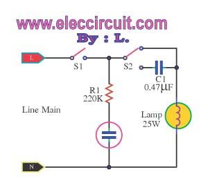
This is an automatic light dimmer circuit that eliminates the need for manual adjustment of light levels. It utilizes a Light Dependent Resistor (LDR) to detect ambient light conditions, which in turn controls a Triac to adjust the brightness...
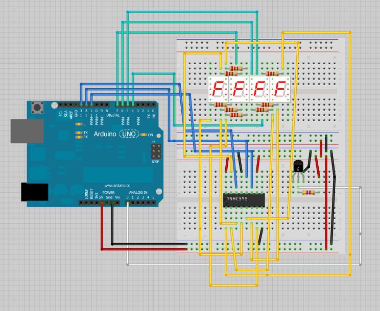
The intention is to utilize this code in future projects involving 7-segment displays. For those interested in learning more about 7-segment displays, additional information can be found in a related post. 7-segment displays are widely used in electronic devices for...
Due to the low coupling coefficient, the primary self-inductance tends to short out the driving signal. However, utilizing a series/parallel set of capacitors for energy coupling increases the input impedance at resonance, thereby achieving good power transfer efficiency. The...
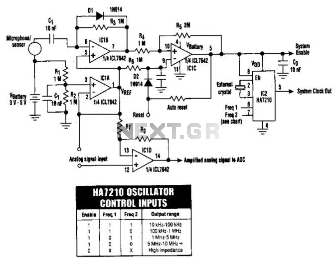
The HA7210 oscillator, in conjunction with the IOL7642 quad CMOS operational amplifier, forms a sleep-mode control circuit. This circuit can enter sleep mode when a logic high is applied to the Reset input or through an RC timer that...
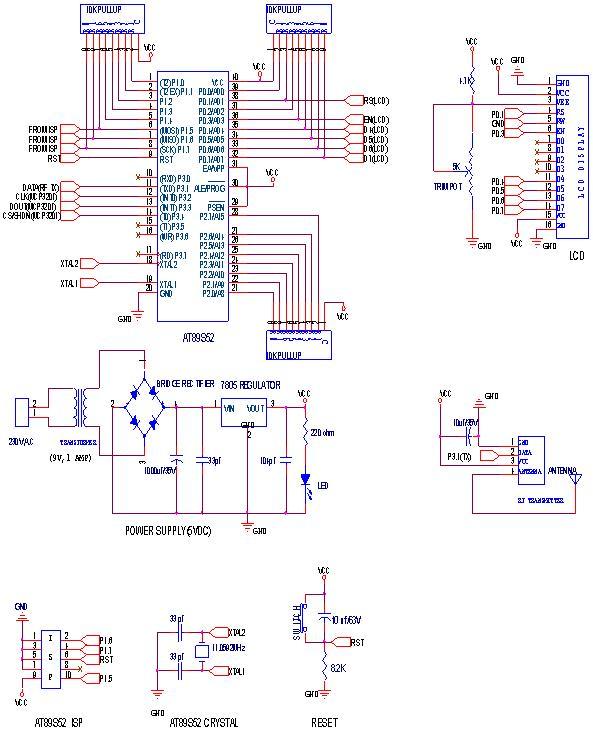
RF Wireless Data Transfer communication circuit diagram. A wireless communication interface was implemented to facilitate data transfer from one point to another using RF technology. The RF Wireless Data Transfer communication circuit utilizes radio frequency (RF) technology to establish a...
The wiring diagram for the clock and radio screen illumination for a 1999 Mercury Sable with a 3.0L VIN U. The vehicle is a Mercury Sable GS, not LS. Assistance is required to identify which circuit in the diagrams...
Warning: include(partials/cookie-banner.php): Failed to open stream: Permission denied in /var/www/html/nextgr/view-circuit.php on line 713
Warning: include(): Failed opening 'partials/cookie-banner.php' for inclusion (include_path='.:/usr/share/php') in /var/www/html/nextgr/view-circuit.php on line 713