Light-seeking robot

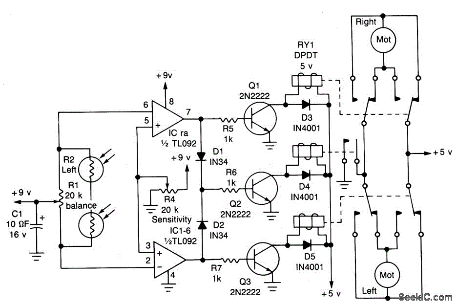
The circuit is designed to seek light, allowing a robot to follow a flashlight in a dark room. Two photocells are used to determine the direction of the robot's movement. Each photocell is connected to an operational amplifier configured as a comparator. When sufficient light falls on photocell R2, the voltage at the inverting input (pin 6) of IC1-a drops below the voltage at the non-inverting input (pin 5), causing the output of the comparator to go high. This activates transistors Q1 and Q2, which in turn energize relays RY1 and RY2, providing power to the right motor. Consequently, the robot will turn left. Similarly, when the light on photocell R3 decreases its resistance, transistors Q2 and Q3 will activate, energizing the left motor and enabling the robot to turn right.
The circuit operates by utilizing two photocells as light sensors, which are strategically placed to detect the intensity of light in different directions. The operational amplifiers serve as comparators, enabling the circuit to compare the voltage levels from the photocells. Each photocell's output is dependent on the ambient light conditions; when one photocell detects more light than the other, it results in a voltage differential that the comparator amplifies.
For instance, when the light intensity on photocell R2 exceeds that of R3, the comparator output transitions to a high state, activating the associated transistors. This action closes the circuit for the relays, allowing current to flow to the right motor, thus prompting the robot to turn in that direction. Conversely, when the light intensity on photocell R3 is greater, the opposite transistors are activated to energize the left motor, causing the robot to turn right.
The design effectively creates a feedback loop where the robot continuously adjusts its direction based on the light source's position. The response time and sensitivity of the circuit can be fine-tuned by adjusting the resistor and capacitor values in the comparator circuit, ensuring optimal performance in various lighting conditions. This light-seeking behavior can be further enhanced by incorporating additional features such as speed control or obstacle avoidance, making the robot more versatile in its navigation capabilities.The circuit is light seeking; it will follow a flashlight around a darkened room. A pair of photocells determine the direction in which the robot will move. Each photocell is connected to an op amp configured as a comparator. When sufficient light falls on photocell R2, the voltage at the inverting input (pin 6) of ICl-a will fall below the voltage at the non-inverting input (pin 5), so the output of the comparator will go high, and transistors Ql and Q2 will turn on. That will enable relays RY1 and RY2, and thereby provide power for the right motor. The robot will then turn left. Likewise, when light falling on R3 lowers its resistance, Q2 and Q3 will turn on, the left motor will energize, and the robot will turn right.
