
Fire Fighting Robot
The robot's movement system relies heavily on the precise control offered by stepper motors. The four-phase stepper motor's operation hinges on energizing the coils in a specific sequence, which can be meticulously controlled via a microcontroller. The design allows for smooth and accurate movement by enabling the robot to navigate tight spaces without collision. The use of optoisolators not only protects the microcontroller from high voltages but also ensures that the control signals are clean and reliable.
The circuit design for controlling the stepper motors incorporates multiple TIP112 transistors, ensuring that each motor coil receives adequate power. By employing a pull-up resistor, the circuit can effectively manage the state of the TIP112 transistors, allowing for precise energization of the coils based on the microcontroller's output. This setup is crucial for maintaining the integrity of the robot's navigation system, especially in environments where precision is paramount.
Overall, the integration of stepper motors, a well-designed control circuit, and the use of salvaged components from Epson printers demonstrates an efficient approach to building a robot capable of navigating complex environments while maintaining the necessary precision in movement.When deciding how to move the robot through the house, the designers realized that precision movement would be necessary in order to avoid touching the walls and receiving penalties. In order to achieve the required precision in movement, it was decided that the robot would utilize stepper motors.
The main benefit of stepper motors is that they are able to turn a specific number of degrees for every step. A four phase stepper motor has four coils that, when energized in a specific sequence, rotate a driving magnetic field which, consequently, rotates a set of permanent magnets. These permanent magnets are attached to a rotor which drives an output shaft. Thus, by pulsing the coils in a certain sequence, a clockwise or counterclockwise movement can be attained.
A change in the coil states (ie. changing from state 2 to state 3 as shown above) results in a single step of the motor shaft. Direction is easily controlled by running through the above sequence either forward or backward. It should also be noted that the coils A and A` are always oppositely charged, as are coils B and B`. By inverting the signals going to coils A and B, the corresponding signals A` and B` can be attained.
Thus, only two control lines are required to place the motor into any one of the 4 possible states. Even though this is an important consideration for certain applications, the controller used in this implementation has a sufficient number of lines to control each coil. Furthermore, because two of the coils are always energized at any given time, the rotor is held into place by the two magnetic fields and hence will not easily slip - even when the motor is not turning.
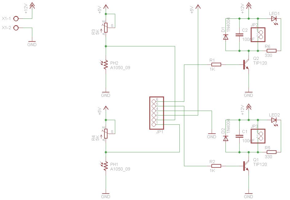
This is another benefit of stepper motors. Figure 2 provides an internal diagram of a typical four phase stepper motor. The stepper motors used for this project were salvaged from surplus Epson printers. The steppers are designed to provide 1. 8 degrees per step (or 200 steps per revolution) and supply a sufficient amount of torque. However, the current requirements of almost any motor are more than a digital output can provide. Because of this requirement, a transistor circuit is needed to drive the motor coils. The circuit shown in Figure 3 is used to drive the motor coils. Because there are a total of eight motor coils in the robot, eight of these circuits are needed. The circuit functions by receiving a digital input from the microcontroller. This signal is fed to an optoisolator in order to separate the low-voltage, low-current microcontroller from potentially dangerous signals in the motor driver circuit. In other words, the optoisolator allows the 68HC12 to control the motors without any physical connection to the driver circuit.
The output side of the optoisolator then drives the base of the TIP112 driver transistor. Just as the stepper motors were, the TIP112 transistors were salvaged from the Epson printers. The TIP112 power transistors are able to supply 50 watts of power, which is more than sufficient to drive the stepper motor coils. When the microcontroller outputs a digital low signal (logic 0), the output side of the optoisolator acts as an open circuit (ie.
no current flows into the collector). The remaining current path is then from Vcc through the pull-up resistor and into the base of the TIP112 driver transistor. This effectively turns the transistor on so that current can flow from collector to emitter. Clearly, current will flow from the 7. 2V battery, through the motor coil, into the collector of the TIP112, and to the emitter ground. Hence, when a logic 0 is sent from the 68HC12 to a given driver circuit, the corresponding coil will become energized.
Inversely, when the microcontroller outputs a digital high signal (logic 1), current will flow from collector to emitter in the output of the optoisolator. This will restrict current from flowing into the base of the driver transistor - causing it to be 🔗 External reference
Related Circuits
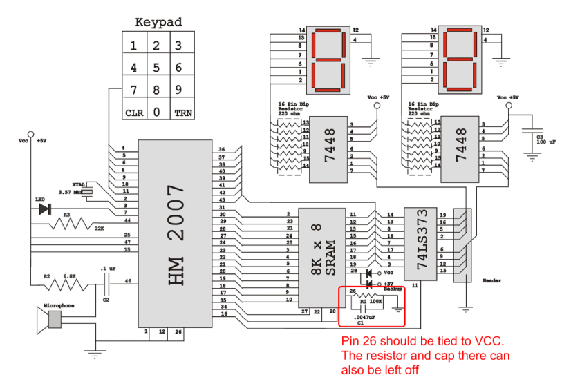
Verify the pin configurations on the datasheets for the integrated circuits used in your project, making necessary adjustments. In this instance, the RAM chip utilized had a non-inverted enable signal on pin 26, while the schematic assumed it was...
This project is based on the Miller solar engine and does not involve any digital electronics. A robot is defined as a "mechanical intelligent agent that can perform tasks independently." Importantly, this definition does not specify any particular form....

The head will be powered by servomotors and constructed from sheet plastic, metal, or plywood. A template for cutting the sheet material can be found at the end of this article. Download the template and compare the size of...
After it runs for a short period, the system shuts off, and there is no injector pulse, although there is spark and fuel pressure. The distributor has been rebuilt, and the EEC has been replaced. It is necessary to...
The figures above illustrate the fundamental concept of a robot, which comprises input and output devices connected to a central processing unit, often referred to as the brain. In this case, the Arduino acts as the brain, controlling all...
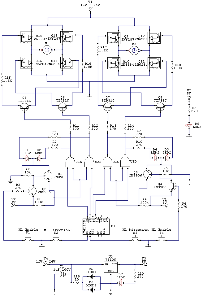
The wiring schematic played a significant role in the robot. This diagram is used to graphically display all the wiring of the motor-controlling micro-components that enabled the robot to physically move forward, backward, left, right, and stop. This diagram...