
LIGHT SEEKING ROBOT
The light-seeking circuit employs a pair of photocells (R2 and R3) that serve as light sensors. These photocells are critical for detecting the intensity of light in their respective directions. The op-amps are configured as comparators to compare the voltage levels from the photocells. When one photocell detects more light than the other, it generates a differential voltage that triggers the appropriate action.
In this setup, the operational amplifier IC1-a plays a pivotal role. It is powered by a suitable voltage supply and has its inverting and non-inverting inputs connected to the photocells. The output of the op-amp drives the base of the transistors Q1 and Q2, which are configured as switches. When the output of the op-amp goes high, it allows current to flow through the transistors, activating the relays RY1 and RY2.
Relays RY1 and RY2 are used to control the power supplied to the motors. When RY1 is activated, it powers the right motor, causing the robot to turn left. Conversely, when RY2 is activated, it powers the left motor, resulting in a right turn. This mechanism allows the robot to navigate towards the light source effectively.
The circuit may also include additional components such as resistors and capacitors to stabilize the operation of the op-amps and transistors, ensuring reliable performance. The design can be further enhanced with features such as adjustable sensitivity for the photocells or feedback mechanisms to improve the robot's directional accuracy. Overall, this light-seeking circuit exemplifies a simple yet effective approach to autonomous navigation based on light detection.The circuit is light seeking; it will follow a flashlight around a darkened room. A pair of photocells determine the direction in which the robot will move. Each photocell is connected to an op amp configured as a comparator. When sufficient light falls on photocell R2, the voltage at the inverting input (pin 6) of ICl-a will fall below the voltag e at the non-inverting input (pin 5), so the output of the comparator will go high, and transistors Q1 and Q2 will turn on. That will enable relays RY1 and RY2, and thereby provide power for the right motor. The robot will then turn left. Likewise, when light falling on R3 lowers its resistance, Q2 and Q3 will turn on, the left motor will energize, and the robot will turn right.
🔗 External reference
Related Circuits
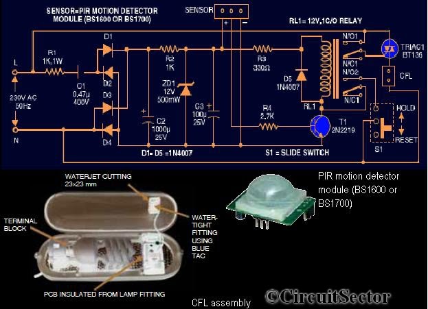
This circuit diagram is based on the PIR motion sensor module BS1600 (or BS1700) designed for security lighting in power-saving mode. If the component is unavailable in local stores, it can be purchased online. A key advantage of this...
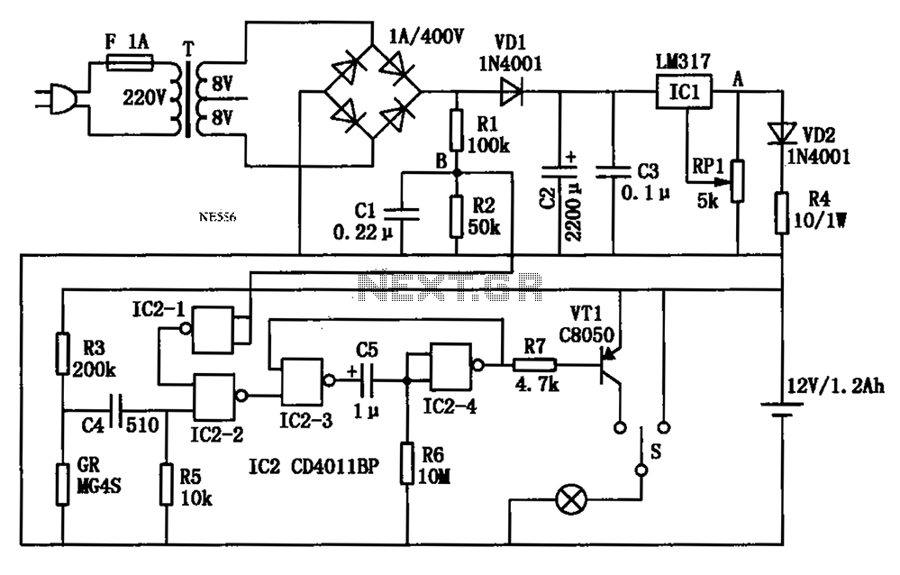
An automatic multipurpose emergency lights circuit is presented. Typically, emergency lights are connected to the mains for standby when fully charged. In the event of a sudden power failure, the ambient light transitions from strong to weak, indicating a...
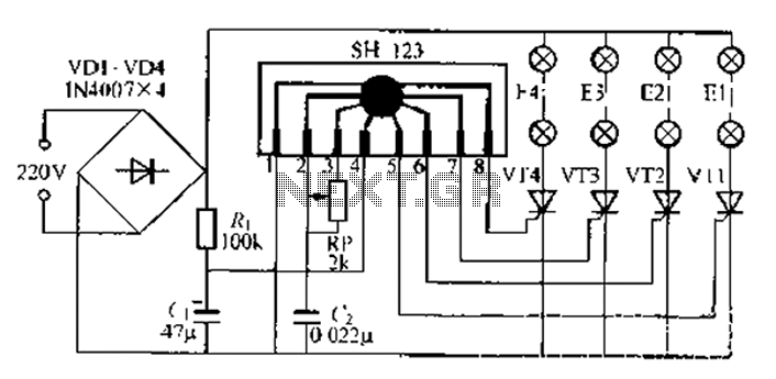
A water Happy Valley-type four flashing lights string controller, electric bollard is designed for use with a type J Ding Japanese lantern. The circuit employs a specific integrated circuit (IC) utilizing CMOS technology. It features a black soft cream...
A decision is being made regarding the wiring of fog lights. There are examples of individuals connecting them directly to the low beam. Fog lights are auxiliary lights designed to illuminate the road immediately in front of a vehicle, providing...
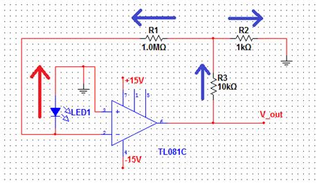
The comparator output drives an LED, and the next step is to sense the intensity of the LED. This lab involves building a light detector circuit using an operational amplifier (op-amp) and a standard light-emitting diode (LED). It is...
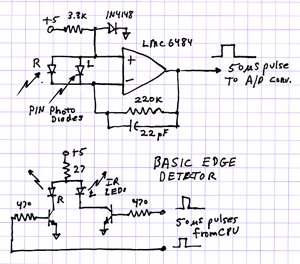
The 2009 Robot Rally highlighted the flaws resulting from a rapid three-week engineering and building project. Time-saving shortcuts in both code and hardware led to multiple failures, including edge detectors, beacon trackers, and line follower reversals. Investigations were conducted...
Warning: include(partials/cookie-banner.php): Failed to open stream: Permission denied in /var/www/html/nextgr/view-circuit.php on line 713
Warning: include(): Failed opening 'partials/cookie-banner.php' for inclusion (include_path='.:/usr/share/php') in /var/www/html/nextgr/view-circuit.php on line 713